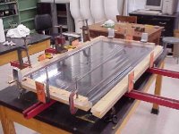
After many mistakes and errors, difficulties with parts and electronics, finally I am done. The ESL is framed with some scrap 2"x1" plexiglass. Of course, the frame is now permanently joined and the ESL is stuck right where it is. It can however tilt 360 degrees in the stand. This ESL and its counterpart were given to my brother, whom I hope will appreciate the effort put into it.
I'm already working on the pair for myself.
I guess that I should state that sonically it sounds beautiful. I'm pretty new in the audio world, so I can safely say that they are the best sounding speakers I've heard. Of course, that could be a little pride shining through.
Enough bragging,
-Dan
I'm already working on the pair for myself.
I guess that I should state that sonically it sounds beautiful. I'm pretty new in the audio world, so I can safely say that they are the best sounding speakers I've heard. Of course, that could be a little pride shining through.
Enough bragging,
-Dan
Attachments
Congratulations!!!
To build electrostatics is not easy...
Bravo!!!
Regards
Jorge
PS:good listenning! 😉
To build electrostatics is not easy...
Bravo!!!
Regards
Jorge
PS:good listenning! 😉
They look great. Where did you get the basic plans and can you give us details on transformers etc. I am starting to get the bug myself. I have a couple of projects to do first but want some stats without the price.
Great Job!!!
I would also like to see the plans that you used or where the idea came from...
Again great job! Beautiful!!!
Happy listening,
Steve
I would also like to see the plans that you used or where the idea came from...
Again great job! Beautiful!!!
Happy listening,
Steve
David and Steve,
I got my first inspiration from an online paper by Mark Rehorst. Then, I used Roger Sanders' Electrostatic Loudspeaker Cookbook for the bulk of the information. I suggest reading both of these.
As for the parts:
The transformers are the most costly. Barry Waldron sells some relatively cheap ($50) transformers specifically for ESLs at www.eslinformation4u.com. But www.tubesandmore.com also sells vacuum tube transformers that can be used backwards to yield a similar effect. I bought both Barry's transformers and the PT-1069 ($40) because I needed two pair (one for me, one for my brother). I wasn't able to do an A-B type test before giving away this pair. But, both worked fine.
If you can get your Mylar from Barry, do so. His Mylar is heat-shrinkable and I couldn't find it anywhere else. Otherwise you'll have to make some sort of stretching jig. Trust me, it is a lot easier to use a heat-gun.
Most of my other materials were purchased from mcmaster-carr.
Total Price is tough to calculate, but less than $400. Of course, that number doesn't account for the hours of toil. All well worth it.
If you need any help with your projects, please don't be afraid to ask.
-Dan
Very nice!
Beautiful work! How big are they?
The last ESLs I built used a 2" PVC pipe frame. The only thing I didn't like about it was the lack of rigidity - not the frame but the speaker. That large mass of perforated steel supported by the edges wobbles like a large drum when I bang on the frame with my hand. It probably doesn't matter because I don't bang on them with my hand while I'm listening to them, but it bugs me anyway. One of these days I'll rebuild by chopping the drivers up into 3 or 4 sections and add more horizontal pipe between them.
Or maybe start from scratch and build a frame from welded steel tubing.
Is your assembly very rigid? Did you use aluminum or steel or something else for the stators?
MR
Mark Rehorst,
Thank you for writing that paper long ago. Now I've lost all of my free time and money, but my ears thank you. 🙂
The stators are 36" x 20" and 22 gauge steel with 5/64" stagered holes. I bought them in 36" x 40" pieces from McMasterCarr. The plexiglas frame has a 5/8" groove cut into it, in which the ~1/4" speaker resides. It is not held tightly at all. No glue, or anything. But they do not wobble inside the frame too much. I guess that I got lucky. If it was a problem I imagine that I could jam some sort of shim in between the frame and the speaker at any trouble spots.
I suggest to anyone that wishes to build a pair of speakers that they utilize the "mirror stand" method of holding it up. It makes it very easy to tilt to the desired listening level. A rigidly vertical support would be unforgiving if one wished to change the layout of a room, or something.
I do not recommend that anyone build theirs with the plexiglas frame. It took a lot of time and precision milling that fortunately I had access to. A similar frame could be thrown together with some timber of your choice. Besides, plexiglas is darn expensive. I was lucky enough to come across a large supply of it for free.
Mark, I am wondering if you could describe your stretching rig. I had to kind of invent my own. I used some of the plexiglass pieces to hold the four sides of the mylar. Then I pulled each piece of plexiglass via a bolt through a frame. The mylar was just just barely above a piece of glass that provided a smooth surface for graphite grinding. The only problem is that the tension is eyeballed and the process takes a lot of time to set up properly, and a lot of clamps/vices are needed. How did you do yours?
-Dan
stretcher
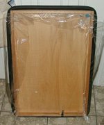
I used a rectangular pneumatic stretcher table of the sort described on my web page (photo attached). The picture shows the bottom side of it and there is some diaphragm material stuck to the tape on the inside of the rim to keep the tape clean. You can see some of the tape along the bottom edge of the rim on either side of the valve stem. Very simple, and very effective!
The large speakers were built using only a heat gun to shrink the film and I am not happy with the result. I get MUCH higher tension from the stretcher table and I don't risk melting a 98% complete speaker's diaphragm. The high tension means I can really crank up the bias voltage and get good sensitivity from the speakers.
The PVC pipe frame speakers have drivers that are 2' wide and 4' high. Too big for a single driver unless you apply some curvature to stiffen the whole thing up (THAT is the real reason Martin-Logan curves the drivers- curving them has little effect on the beaminess). If I were going to do it again, I'd use a pneumatic stretcher. Bicycle tire tubes will stretch quite a lot!
MR
Attachments
Mark,
Your table looks like a good idea. I may want to try it for my next batch (sigh). I remember reading about it in your paper, but I thought it wasn't a very good idea at the time. My stretching table does have a little bit of a problem with pressure points. Sometimes my stretching will cause parts of the Mylar to rip, while other parts are much looser.
Thanks for your picture.
-Dan
The stretcher you used is a variation of the metal bars with screws that Roger Sanders used in his Speaker Builder (or was it Audio Amateur?) articles many years ago. I tried it and discovered that since the metal bars will flex, you always end up putting lots of tension on the corners of the film and very little at the center. This can be seen when the diaphragm fails because of over tightening -it is always split along the corner-to-opposite- corner axis.
The bicycle tire tube tends to equalize the tension across the whole diaphragm because as tension increases in one area, the air in the tube will be pushed to an area with less tension. The result is very high, more or less even tension across the whole surface.
The pneumatic stretcher would allow all sorts of interesting fooling around- you could built it right into a speaker and then adjust the tension (air pressure) to look for audible effects of resonance, and etc. while the speaker is playing...
MR
one more thing
Set-up time...
It takes just a little practice to set the film up right on the stretcher so that you get a completely wrinkle free result. Once you have mastered the technique (<10 minutes) you can throw a new diaphragm down and stretch it tight in under a minute. no clamps, no fooling around.
You spread the film out on the table surface, getting as smooth as possible, then start wrapping it around to stick to the tape, starting near the center and working your way toward the corners. You don't need to apply any more muscle than necessary to simply get the film pulled over and stuck to the tape. Don't worry about small wrinkles - they won't be there when you're done.
Try it once and you'll never fool around with clamps, heat guns, or other Rube Goldberg contraptions again.
MR
Mark,
Thanks for the input.
What type of tape are you using? It seems that the tape will have to hold as much tension as you are putting on the membrane. People have suggested plain ole masking tape, but I don't know what they are talking about. Maybe its the humidity, but masking tape holds about as much as a post-it note.
-Dan
tape
I use some stuff that is sticky on both sides. I bought it in Japan, but it is just household stuff. You can use carpet tape.
It doesn't have to hold the entire tension applied to the film- that is why the tape is placed inside the rim of the table- the film bends over 3 edges which greatly diminishes the tension seen by the tape. It's like wrapping a piece of string around a piece of pipe and pulling on it. It takes almost no effort at all to keep the string from slipping, even if you pull real hard on the opposite end.
MR
Mark,
Ahhhh! I did not realize that the Mylar was wrapping around as such. This sounds like a much better way to tension. Carpet tape sounds like a viable option. Of course, I'll have to build the rig first...
A problem with my stretching rig is the mylar's slipping. Sometimes it will creep out from under the plexiglas. Obviously this could be fixed by using many more clamps, but I exhausted my supply at what I thought was just enough. So, I didn't bother to get anymore.
More questions: What do you use as a flat surface behind the Mylar to grind in graphite? Do you do so while in the stretching rig?
Thanks
-Dan
The top side of the table has a sheet of smooth plastic laid over it. I apply the graphite to the film while the film is under tension. The stator assembly that I glue to the stretched film is the side with the diaphragm electrical contact.
There is a small hole all the way through the table to allow air trapped under the diaphragm to escape, otherwise, you get a nice little pillow when you stretch the film.
MR
There is a small hole all the way through the table to allow air trapped under the diaphragm to escape, otherwise, you get a nice little pillow when you stretch the film.
MR
More stupid questions.
If I was to build a table for such a stretching rig, I realized that it would have to be at least 21"x37". Where do you get a tire that is that big? It would have to be 116" in circumference. A 26" tire is only about 80" in diameter. Would it stretch enough?
Thanks
-Dan
If I was to build a table for such a stretching rig, I realized that it would have to be at least 21"x37". Where do you get a tire that is that big? It would have to be 116" in circumference. A 26" tire is only about 80" in diameter. Would it stretch enough?
Thanks
-Dan
- Status
- Not open for further replies.
- Home
- Loudspeakers
- Planars & Exotics
- Finished ESL picture (finally!)