I have several power tetrodes(transmitter tubes) that I want to build an amp out of. Unfortunately, the datasheets only give the Grid voltage Vs Plate voltage instead of the plate current vs plate voltage graph. Is there a way to mathematically derive the required graph?
Any help would be appreciated!
Any help would be appreciated!
If you want to do it mathematically, you could get some indicative curves by using LtSpice.
Spice curvetracing how-to:
:: View topic - Tube plate curves
Tube Simulation with PSPICE: Tips, Tricks, Techniques
This of course requires that you have pentode spice models for the tubes.
If not, there are even ways to generate these form just a screenshot of plate curves:
Model Paint Tools: Trace Tube Parameters over Plate Curves, Interactively
Below is an example of curve traces from Ltspice with El84/6BQ5 wired as pentode and triode compared to the published curves.
Svein.
Attachments
Thanks for the Suggestion; As promising as the software looks, my computer won't run it for some reason... I've clicked on the executable several times and nothing happens 🙁.
Run paint tool
Hey,
make shure you install a JAVA runtime version >= 1.4 on your computer. Aslo check the PATH variable like:
windows:
echo %PATh%
Should include a PATH like C:\programs\JAVA\1.5.15\jre\bin
UNIX:
echo $PATH
Should include a PATH like /opt/java/1.5.15/jre/bin
simply check this by typing in at the shell "java -version". There should be the installed version printed out.
To start model patin type in:
java -jar paint_kip.jar ( for pentodes) or java.jar paint_kit.jar ( for triodes )
Well, it´s not my farvorite tool. I never bring the curves to concident usind all the slides. For triodes try to use "curve captor". It´s easy, fast and produce a very matching space output.
Have fun..
Karsten
Karsten21 - Thanks for the tips. Unfortunately, I still can't get the program to work.
Serge66 - I can only find the datasheet; there are no triode curves.
Unfortunately, the datasheets for the tubes I want to use do not have a Plate V - Plate current plot. They only provide a grid V- plate V plot; I'm not too sure how to go about this since all the methods of deriving the triode curve rely on the plate V-plate current...
Any thoughts?
What are the tubes you're using?
Ham radio resources would be another avenue I'd check out...hams have a lot of info about transmitting tubes of all kinds, and the old ARRL Handbooks were great sources of tube operation info.
Ham radio resources would be another avenue I'd check out...hams have a lot of info about transmitting tubes of all kinds, and the old ARRL Handbooks were great sources of tube operation info.
Last edited:
I am looking into using the 4x150 and various other 4-xxxA series tubes that I have lying around. Unfortunately, these tubes were never designed for use in triode mode so the triode curves were never documented.
I am looking into using the 4x150 and various other 4-xxxA series tubes that I have lying around.
Unfortunately these tubes don't work too well as triodes. The maximum screen grid voltage for the 4X150 is 300 volts. The maximum for the 4CX250 is 400 volts. I blew up a 4CX250 to find out that this rating is real. I have several more. They will probably wind up in a 2 meter linear amp.
Thanks for pointing that out; I completely forgot to look at the screen voltages! I will need to look over the datasheets for several other tubes before deciding.
Now for the stupid questions/ideas/suggestions:
Would it work:
- Grounded grid mode
- Strapping the two screens together
- Leaving the unwanted screen disconnected
- Grounding the unwanted screen
Any info is appreciated!
Now for the stupid questions/ideas/suggestions:
Would it work:
- Grounded grid mode
- Strapping the two screens together
- Leaving the unwanted screen disconnected
- Grounding the unwanted screen
Any info is appreciated!
As I have said before, any time you venture from the accepted norm you must be prepared to experiment. The voltages involved with tubes of this type are instantly lethal. The transformers required to build a big amplifier with these tubes are not redilly available either, and won't be cheap. Unless you have plenty of experience with tube amplifier construction, I would look at some more conventional tubes.
There are no off the shelf schematics to use with this type of tube. In fact I don't even remember seeing them used in an audio application. I would guess one of the reasons might be the forced air cooling requirement. These tubes require a substantial amount of air blown up through the chimney (a speciallized socket). This won't be quiet. These tubes are of the "external anode" variety. This means that the exposed metal that you see IS the plate and it operates at a high voltage. I have seen some ham radio operators using liquid cooled closed loop systems similar to that used in a high end gaming computer with 2C39's. They use distilled water or very thin synthetic motor oil.
Assuming you get past all of these hurdles, how do you connect the tubes?
I must admit that I blew up my 4CX250 and may have fried a 4CX350 (although it may have been dead when I got it) about 10 years ago when I knew much less about tubes than I do now. At that time I believed that the only way to good sound was through triode amplification, so I tried it on several tubes that were clearly not suited for triode use. Several tubes died as a result of these experiments. I now have a few good sounding pentode amplifiers and more are coming.
The data sheet shows 3 different operating points for audio amplifier use. They are all tetrode wired, so this is where I would start. After the amplifier is working well enough for measurements, you could apply some local feedback around the output stage to "triodeize" it. I may try this approach some day, but there are countless other tubes that I plan to experiment on first.
The ideas that you suggest may be grounds for some experiments. I don't know of any simple answer other than to try it. Even for an experienced experimenter, I would strongly suggest trying the idea on a much smaller scale (and supply voltage) first before unleashing a 1KV+ fireball!
Grounded grid was popular with RF amplifiers. It has been used succesfully in audio amplifiers. In both cases this was done with true triodes. It may be possible to use a floating screen supply, or even a fixed screen supply since the drive voltage requirements are very low.
Connecting G1 and G2 together to create a high Mu triode has been done before. There is some mention of this connection is WWII vintage data sheets and I have seen it mentioned here and in literature. The schematics showed an 807 tube. My experiments with this connection have all ended with some burnt parts. I suspect that unintended RF oscillation was the cause, but nothing lasted long enough to troubleshoot.
Leaving any element in a tube unconnected is an invitation to undesired results. It is sort of like leaving a CMOS gate open. Depending on leakage currents which vary from tube to tube you could get anything from no current to full conduction, or some random state in between. Most tubes will do nothing with the screen grid disconnected.
Any tube having a screen grid usually requires a positive voltage applied to it to get any current flow.
There are no off the shelf schematics to use with this type of tube. In fact I don't even remember seeing them used in an audio application. I would guess one of the reasons might be the forced air cooling requirement. These tubes require a substantial amount of air blown up through the chimney (a speciallized socket). This won't be quiet. These tubes are of the "external anode" variety. This means that the exposed metal that you see IS the plate and it operates at a high voltage. I have seen some ham radio operators using liquid cooled closed loop systems similar to that used in a high end gaming computer with 2C39's. They use distilled water or very thin synthetic motor oil.
Assuming you get past all of these hurdles, how do you connect the tubes?
I must admit that I blew up my 4CX250 and may have fried a 4CX350 (although it may have been dead when I got it) about 10 years ago when I knew much less about tubes than I do now. At that time I believed that the only way to good sound was through triode amplification, so I tried it on several tubes that were clearly not suited for triode use. Several tubes died as a result of these experiments. I now have a few good sounding pentode amplifiers and more are coming.
The data sheet shows 3 different operating points for audio amplifier use. They are all tetrode wired, so this is where I would start. After the amplifier is working well enough for measurements, you could apply some local feedback around the output stage to "triodeize" it. I may try this approach some day, but there are countless other tubes that I plan to experiment on first.
Would it work:
The ideas that you suggest may be grounds for some experiments. I don't know of any simple answer other than to try it. Even for an experienced experimenter, I would strongly suggest trying the idea on a much smaller scale (and supply voltage) first before unleashing a 1KV+ fireball!
- Grounded grid mode
Grounded grid was popular with RF amplifiers. It has been used succesfully in audio amplifiers. In both cases this was done with true triodes. It may be possible to use a floating screen supply, or even a fixed screen supply since the drive voltage requirements are very low.
- Strapping the two screens together
Connecting G1 and G2 together to create a high Mu triode has been done before. There is some mention of this connection is WWII vintage data sheets and I have seen it mentioned here and in literature. The schematics showed an 807 tube. My experiments with this connection have all ended with some burnt parts. I suspect that unintended RF oscillation was the cause, but nothing lasted long enough to troubleshoot.
- Leaving the unwanted screen disconnected
Leaving any element in a tube unconnected is an invitation to undesired results. It is sort of like leaving a CMOS gate open. Depending on leakage currents which vary from tube to tube you could get anything from no current to full conduction, or some random state in between. Most tubes will do nothing with the screen grid disconnected.
- Grounding the unwanted screen
Any tube having a screen grid usually requires a positive voltage applied to it to get any current flow.
I have several power tetrodes(transmitter tubes) that I want to build an amp out of. Unfortunately, the datasheets only give the Grid voltage Vs Plate voltage instead of the plate current vs plate voltage graph. Is there a way to mathematically derive the required graph?
Any help would be appreciated!
This won't help for triode mode, but you can simply plot the load lines on the constant current charts (Vg vs. Va) to get a pretty good idea of the operating range in tetrode mode, as shown in this post:
http://www.diyaudio.com/forums/tubes-valves/94663-304tl-based-class-4.html#post1916598
I agree with tubelab about using these things in tetrode mode for the most part (I have had good luck with the 4-65a in triode up to ~800V). Tetrode connection with local plate-grid feedback for triode emulation seems like a natural for these high voltage, high impedance tubes.
Michael
The screen grid can be removed from operation by placing a blocking diode connected to the plate. No current can flow so the screen grid voltage does not restrict operation above it.
Tubes
Topic 2.
I ran triode curves on a 4x150A this way and came up with an Rp of about 450 ohms and Av of 5. If I run across the graph I'll post it. -40 V bias at 400V gave about 100ma. plate current if I remember right. The curves were so steep that I think holding the proper bias would be difficult.
I also have a couple of pipes that can act as coolers/connectors? that have fingers arount the inside which slip over the cooling fins. They are about 6" long and again, IIRC allow about 80 watts to be dissipated without forced air.
Mike, I'm working on a 4-65A amp right now. Can you post a schematic or e-mail me one? I was thinking of using P-G feedback also.
Hey guys,
I really appreciate all the help/info you guys have provided! I will need to do some more research before deciding on the specific tube/design. I am leaning towards a fixed screen supply but I'll need to read into it further.
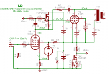
dshortt9 - I am also working on a 4-65A amp. The schematic can be found here:
http://www.diyaudio.com/forums/tubes-valves/144767-class-a2-direct-mosfet-coupled-se.html
PM Michael Koster if you need any additional info, he's extremely helpful!
I really appreciate all the help/info you guys have provided! I will need to do some more research before deciding on the specific tube/design. I am leaning towards a fixed screen supply but I'll need to read into it further.
dshortt9 - I am also working on a 4-65A amp. The schematic can be found here:
http://www.diyaudio.com/forums/tubes-valves/144767-class-a2-direct-mosfet-coupled-se.html
PM Michael Koster if you need any additional info, he's extremely helpful!
Mike, I'm working on a 4-65A amp right now. Can you post a schematic or e-mail me one? I was thinking of using P-G feedback also.
Here is a work-in-progress P-G "Schade" feedback version of the 4-65A triode amp. This has a much lower effective anode resistance than the triode version (<500 ohms vs. ~1500 ohms) so is using a 5K OPT.
Briefly, the MOSFET is a sort of gyrator for the driver anode, and also acts as a source follower to drive the grid, allowing the P-G feedback path to be the only dynamic (AC) load for the driver. The driver functions as a V/I converter loaded by the plate-grid feedback through the feedback resistor R5. The 4-65a control grid current is only 15-20mA in this but it's g2 can draw close to 100mA on peaks.
I am in the early breadboard phase with this so it's still highly experimental.
Cheers,
Michael
Attachments
Last edited:
- Status
- Not open for further replies.
- Home
- Amplifiers
- Tubes / Valves
- Finding triode curves