Orthogonal Parabolic
Found these formulae in a patent (5,765,934) describing orthogonal parabolic reflectors:
Y=2{f(f+X)}.sup.1/2 where -f.ltoreq.X.ltoreq.0 Eq. (1)
Y=2{f(f-X)}.sup.1/2 where 0.ltoreq.X.ltoreq.f Eq. (2)
where f is a focal length of the paraboloid located on X-axis of a coordinate (X, Y);
I barely understand parabolic math! Anyone understand this one?
FYI - That same patent has some very interesting ideas which seem to apply directly to what we're trying to do with our reflectors - make non-point-source light behave as if it is. One thing which caught my attention was the use of optical fibers. Here's an excerpt:
The optical performance of a projection type display using a light valve greatly depends on the illumination optical system that illuminates the light valve, particularly the characteristics of the light source. Liquid crystal projectors use a light source such as a tungsten halogen lamp, metal halide lamp, and xenon lamp. These light sources are not an ideal spot light source, while the light emitted from a non-ideal light source is condensed by a reflecting mirror such as a parabolic mirror, elliptic mirror, and spherical mirror that have a substantially ideal shape. As a result, the image projected on the screen is not uniform. Manufacturing variations of the lamps are also a source of significant differences in efficiency, color temperature, and useful life of the lamp. Such differences cause non-uniformity in brightness and color of the projected image, deteriorating the quality of the projected image.
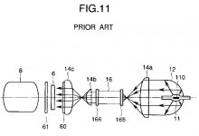
In order to solve the aforementioned problems, Japanese Patent Preliminary Publication No. 4-204883 discloses a liquid crystal projector using optical fibers. FIG. 11 shows a general construction of the prior art light source apparatus for the liquid crystal projector.
An illumination system is constructed of a metal halide lamp 11 and reflector 12, and the light emitted from the system is condensed by a lens 14a. The light is then incident upon a bundle 16 of optical fibers to which connectors 165 and 166 are connected. The bundle 16 of optical fibers includes a plurality of element optical fibers, and the arrangement of the element optical fibers at the end at which the light is incident are not correlated at all with the arrangement of the element optical fibers at the end at which the light is emitted. This ensures that light having uniform distribution of intensity throughout the overall light pattern is emitted from the light-emitting end of the bundle 16 even if the intensity of light at the light-incident end of the bundle 16 is non-uniform. The light is diverged by a lens 14b before illuminating a liquid crystal panel 6 which has a condenser lens 14c and two polarizing plates 60 and 61. The output of the polarizing plate 61 then passes through a projection lens 8 to project an image onto the screen. The projected image with a uniform intensity is thus obtained.
My head hurts, but its a good sort of hurt...
Found these formulae in a patent (5,765,934) describing orthogonal parabolic reflectors:
Y=2{f(f+X)}.sup.1/2 where -f.ltoreq.X.ltoreq.0 Eq. (1)
Y=2{f(f-X)}.sup.1/2 where 0.ltoreq.X.ltoreq.f Eq. (2)
where f is a focal length of the paraboloid located on X-axis of a coordinate (X, Y);
I barely understand parabolic math! Anyone understand this one?
FYI - That same patent has some very interesting ideas which seem to apply directly to what we're trying to do with our reflectors - make non-point-source light behave as if it is. One thing which caught my attention was the use of optical fibers. Here's an excerpt:
The optical performance of a projection type display using a light valve greatly depends on the illumination optical system that illuminates the light valve, particularly the characteristics of the light source. Liquid crystal projectors use a light source such as a tungsten halogen lamp, metal halide lamp, and xenon lamp. These light sources are not an ideal spot light source, while the light emitted from a non-ideal light source is condensed by a reflecting mirror such as a parabolic mirror, elliptic mirror, and spherical mirror that have a substantially ideal shape. As a result, the image projected on the screen is not uniform. Manufacturing variations of the lamps are also a source of significant differences in efficiency, color temperature, and useful life of the lamp. Such differences cause non-uniformity in brightness and color of the projected image, deteriorating the quality of the projected image.
In order to solve the aforementioned problems, Japanese Patent Preliminary Publication No. 4-204883 discloses a liquid crystal projector using optical fibers. FIG. 11 shows a general construction of the prior art light source apparatus for the liquid crystal projector.
An illumination system is constructed of a metal halide lamp 11 and reflector 12, and the light emitted from the system is condensed by a lens 14a. The light is then incident upon a bundle 16 of optical fibers to which connectors 165 and 166 are connected. The bundle 16 of optical fibers includes a plurality of element optical fibers, and the arrangement of the element optical fibers at the end at which the light is incident are not correlated at all with the arrangement of the element optical fibers at the end at which the light is emitted. This ensures that light having uniform distribution of intensity throughout the overall light pattern is emitted from the light-emitting end of the bundle 16 even if the intensity of light at the light-incident end of the bundle 16 is non-uniform. The light is diverged by a lens 14b before illuminating a liquid crystal panel 6 which has a condenser lens 14c and two polarizing plates 60 and 61. The output of the polarizing plate 61 then passes through a projection lens 8 to project an image onto the screen. The projected image with a uniform intensity is thus obtained.
My head hurts, but its a good sort of hurt...
Good stuff, mycamel,
The only thing I don`t understand is the optical fiber part. how are optical fibers going to be beneficial to the distribution of light? I must be reading it wrong...
Also, how big would you guess those lenses are they are using? 3 or 4 Inches?
mitch
The only thing I don`t understand is the optical fiber part. how are optical fibers going to be beneficial to the distribution of light? I must be reading it wrong...
Also, how big would you guess those lenses are they are using? 3 or 4 Inches?
mitch
Mitch,
The reason for the optical fibres is to increase uniformity in the light hitting the LCD.
The idea behind them is that the optical fibres receiving the light from a particular area do not all output into the same area of the LCD. They are mixed and moved around so that any hotspots coming out of the light module are distributed throuought the area of the LCD.
Bill.
ok, I get that now. However, I`ve been searching all over the internet and I can`t find out what an optical fiber is or what it looks like. Care to share?
Mitch
Mitch
Mitch said:ok, I get that now. However, I`ve been searching all over the internet and I can`t find out what an optical fiber is or what it looks like. Care to share?
Mitch
Here's some starter info.
Optical fibre is a (usually) very thin strand of high quality optical glass surrounded by a sleeve of a material with a different index of refraction . Then a protective coating is applied to protect from mechanical damage The idea is light rays entering at one end travel the length of the fibre with very little attenuation. Many telephone long distance links are fibtre optic. A fiibre optic cable can carry thousands of times as much as comparable copper lines or coaxial cables. Many buildings have a fibre optic backbone cabling system for high speed computer/ communications. One of the many advantages of fibre optic cables is the fibre can be bent around a shallow radii and the light inside is not lost or disturbed.
It follows the curve with very little loss by a process known as total internal reflection.
An orthogonal parabolic reflector is not a parabolic reflector. It takes a line source of light for example a long halogen fillament or any other long type filament, collects the light and focuses that light to a point. It does not in itself give you parallel rays as a regular parabolic reflector does. The advantage is it is the only type of reflector that can focus a line source light. Other types of reflectors such as elliptical or parabolic require a point source for best results. There is information and drawings on a orthogonal reflector in the video projector part 1 thread.
remp said:There is information and drawings on a orthogonal reflector in the video projector part 1 thread.
I should've used the search function - Good stuff there. Thanks!
Hi Gunawan,
Such a reflector is only truly parabolic along the central axis of each face. As you move towards the corners, each face only has parabolic characteristics in one dimension. In the other dimension, the face is a flat plane - giving the output beam a "floodlight" characteristic..
If LCDs were more forgiving of viewing angle, and we were using a primary objective that was larger compared with the LCD, then it would be good enough. But, even with fresnels guiding the output beam, much of the light coming from the LCD would never reach the objective.
Bill.
Wha-ho! So light is actually traveling inside this fiber until the other end? Thats nifty.
Thanks for the help, remp and mycamel.
Thanks for the help, remp and mycamel.
Hard to imagine one fibre so thin you can hardly see it can handle millions of phone calls all at once or deliver gigabytes of computer data at the speed of light.
And its a relatively simple DIY project if you have a need.
A fibre optic bundle is not the only way to even out light from an imperfect reflector. A short optic quality glass rod with square cut and polished ends is used in many situations where imperfectly distributed light has to be made perfectly even. From what I have read on the internet many 3 panel projector manufacturers use a glass rod for this purpose. Will find the details if anyone is interested.
Hey, if somebody would draw up a more detailed diagram of just the fiber optic part of (fig 11) from page 3, that would be neato... cause it wasn`t very helpful to us who know next to nothing about fiber optics. I have been researching though and I am learning a little.
Mitch
Mitch
Orthogonal Parabolic reflector
It seems like this is the kind of reflector we would need.
I tried looking at the images at the US patent website for the projection display but my browser would not load the images.
Is an orthogonal parabolic reflector shaped differently than a regular parabolic reflector?
How come with Marklar's reflector the light is all concentrated to that small point? (Looks like an ellipsiodal)
My reflector can burn cardboard but is that enough?
I am feeling some vibes right now. Not all of the light is focused properly with my reflector, but light shines everywhere. (I feel only a portion of the light is being utilizes)
Seems hard to find the focal point of this light becuase it is not focused in an orderly fashion
It doesn't seem like finding an "orthagonal parabolic reflector" is an easy task, or finding any suitable reflector!
I feel something homebrew will never do. Well at least we can try anyway.
Sigh sigh sigh
Don't forget....
I ask a lot of questions so you will have to put up with me for now.
I will post anything I can to help out with DIY video projection
This video section of this web site is all about homemade lcd projectors
and it all started with one post!
---------------------------------------------
Hi,
If there is anybody out there that is interested in sharing ideas on DIY video projectors, please let me know. I have several sources for parts, info and theory. I'd like to network with others who'd like to try this or who has worked on this type of project in the past.
-----------------------------------------------
Does 3251 replies to this topic answer your question?
😀 😀 😀
Woneill,
I know rectangular-parabolic reflector is not perfect, but it's very easy to make compared with circular-parabolic reflector.
Even with perfect circular-parabolic reflector which can produce perfect parallel rays, it still have problem with direct rays from light source which it's not parallel rays (the rays spreading away).
BTW, I found site explaining: How to draw a parabolic curve without any knowledge of Mathematics, here:
http://www.cc.jyu.fi/~hvirtane/cooker/node8.html
Hi Gunawan,
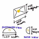
If the bulb is mounted with the filament longitudinally, then most of the light will be emitted transverse to the filament - into the reflector and out of the front. See my crap picture. This way tends to reduce the amount of light coming out of the front of the reflector directly from the filament itself. Though it doesn't eliminate it.
This is actually the problem with the theory behing the ortho-parabolic reflector. Its design is not to collect and focus MOST of the light from the bulb: its design is to maximise the amount of light that CAN be focussed.
Thus, while you WILL get a point source of light, you will also waste probably 90% of the light from the bulb in getting it.
The best bet, if you want the purest point source of light, is to use an elliptical reflector to bring the light to a point(ish), and use a small diaphragm to mask off everything except the brightest center of that point. You will probably not loose much more than you would if you went for the ortho-parabolic, and an elliptical reflector is easier to make/find.
Having said all that, with the LCD diffusing the output, I STILL maintain that treating the LCD as a self contained light source that decouples the output optics from the lamp optics, and trying to get an even illumination across its back face with roughly parallel light is more important than striving for ultra high optical quality in the light source phase.
A rough point source plus two fresnels, or a rough parallel source plus a single fresnel (before or after the LCD, dependent on taste) should give the LCD a decent enough illumination. If the majority of the light that gets through the LCD is fed to the primary objective then a high quality image should result.
Different screens have different effects - one of my sharp panels (8" QA 1100) is almost opaque, while another (10" QA 1000) is almost transparent. My 8" Spectra C is somewhere in between, and my DOA 10.4" Proxima 822 behaves like a pure diffraction grating. The opaque Sharp panel benefits most from parallel rays and putting a large lens immediately after it (fresnels work here, but I have recently acquired an 8" diameter lens from an elliptical stage light - awesome...) The others seem to be easy enough to work with in either configuration.
I seem to be rambling - so I'll stop now...
Bill.
Attachments

How about this setup:
http://gwidijanto.fcpages.com/reflector1.htm
It can utilize wasted direct rays and all light goes to parabolic reflector before hitting fresnel panel.
http://gwidijanto.fcpages.com/reflector1.htm
It can utilize wasted direct rays and all light goes to parabolic reflector before hitting fresnel panel.
Hi Gunawan,
Interesting diagrams - I like them, but they hilight a problem with parabolic reflectors that I have been mulling around with for a while: both your and my diagrams show the removal the light coming directly from the filament at the center of the apparatus.
The end result is the opposite of a hotspot - a black hole right at the center of the beam...
Would it be worth sunbstuting a small convex lens for the little blocking mirror in your diagram? If its focal length were suitable, and its diameter small enough (<= the diameter of the bulb), it would only affect rays coming from the front of the bulb, and collimate them to the same degree as the rear main reflector. The glass of the bulb itself would destroy the coherence any rays reflected through it from behind, so not much would be lost here.
What do you think?
Bill.
there is only one thing you need to know about reflectors.
light ONLY reflects at 90 degree angles.
woneill, your picture is wrong. rays reflect at right angles when they hit a reflective surface. that reflector would end up focusing the light into a point out in front of the reflector.
i have some good tutorials and reading about these things on my site, which im working on getting back up. if anyone could help me out, i could have it up much sooner. email me if you are interested.
- Status
- Not open for further replies.
- Home
- General Interest
- Everything Else
- The Moving Image
- Lighting and OHP
- Finding a suitable reflector