I cannot find what I did wrong in this power supply and it's making me crazy. Can you un-crazy me?
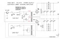
Everything is out in the open, no hidden wires and it follows the long time published PSU from 2005 except I had to use CL40 instead of CL60 NTCs (they handle more amperage but put forth less resistance.)
I have a bunch of pictures, maybe someone likes this kind of puzzle?
Everything is out in the open, no hidden wires and it follows the long time published PSU from 2005 except I had to use CL40 instead of CL60 NTCs (they handle more amperage but put forth less resistance.)
I have a bunch of pictures, maybe someone likes this kind of puzzle?
Attachments
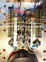
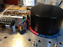
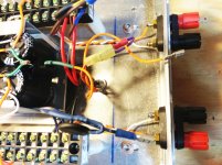
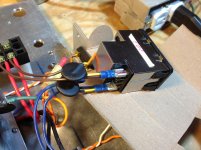
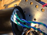
I guess there really is a set of hidden wires...the red and black primary input power wires go under the bank of 15,000uF caps to be hooked up to a Corcom IEC module. The blue and green emerge from under the shield and go to the bridge rectifiers...
It is pretty much a direct part-to-part translation of the F5 power supply and I cannot get my dim bulb tester to go out...the PSU never charges up...😕
It is pretty much a direct part-to-part translation of the F5 power supply and I cannot get my dim bulb tester to go out...the PSU never charges up...😕
Attachments
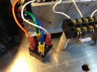
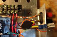
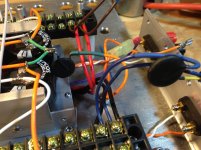
A few more pictures of the IEC and grounding. Note all ground wires are orange and go to a single point on the chassis floor...
Attachments

Are you sure the primaries are wired up correctly? I could see a few places where the wiring could be optimised, but nothing glaringly wrong.
You could try disconnecting the rectifiers and see if the problem persists.
You could try disconnecting the rectifiers and see if the problem persists.
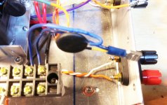
Why do you have the center ground wires going to each bank of + and -? And the long white wires connecting both banks does not look correct to me. Snip those wires and also the negative going to the banks. With the terminal strips being used it is a little hard to figure out the whys and whats. Only positive should be on one strip and on the other strip only negative voltage in relationship to the center ground. The center ground should not be hooked up to anything else. Other than the IEC ground which actually has nothing to do with correct voltages, only a hum and safety aspect.
If you look at the schematic you will see the two banks are not connected to each other other than the 2.2K resistors which also has nothing to do with the circuit. Those resistors are bleeder resistors. You can snip them until you get the PS section working correctly and bleed the caps down manually with a resistor.
About the layout of the center ground lines in orange, I meant to mimic the F5 psu layout where they leave the bridge rectifiers, travel along the caps, meet and then pass through a NYC before hitting star ground.
The white wires that crossover the cap bank are to afford a V+ AND V- attachment to both (F6) boards.
The white wires that crossover the cap bank are to afford a V+ AND V- attachment to both (F6) boards.
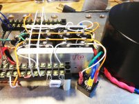
The Orange leads that go to the barrier strips are there to afford connection of the boards to signal negative...
And the orange and white twisted pair is for the boards to hook to the speaker terminals - at the moment these are obviously not connected to anything.
And the orange and white twisted pair is for the boards to hook to the speaker terminals - at the moment these are obviously not connected to anything.
Thank you guys very much for taking a shot, I thought Craig had spotted a false assumption for me, that's usually the culprit.
How long should I wait to see if the bulb dims? I have only been waiting perhaps 6 seconds... I'm very worried about burning something up!
How long should I wait to see if the bulb dims? I have only been waiting perhaps 6 seconds... I'm very worried about burning something up!
Secondary Phase
The secondaries could be out of phase. For just one of the secondaries connection to the bridge rectifier, move the blue lead to the lug where the green lead is now connected and move the green lead to the lug where the blue lead is now connected.
The secondaries could be out of phase. For just one of the secondaries connection to the bridge rectifier, move the blue lead to the lug where the green lead is now connected and move the green lead to the lug where the blue lead is now connected.
Out of phase secondaries are not a problem, as the rectification process is
symmetrical and one-way only. It is important that both leads from the
transformer to the rectifier belong to the same secondary coil.
symmetrical and one-way only. It is important that both leads from the
transformer to the rectifier belong to the same secondary coil.
according to pictures , everything is wired correctly
however , to be sure that primaries are wired properly, do this :
-disconnect one secondary wire from each diode bridge, so bridges and C bank are disconnected from xformer
-power xformer through bulb tester ;
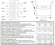
if everything is OK - bulb tester will be dark , then confirm 18Vac on each secondary
power it off , check for shorts at bridge - input side , same as output side ; best to do that with diode/beep function on your DMM , so you can observe charging of cap banks on meter screen (disconnect bleeders for that test)
if that is ok - connect again bridges to xformer , leave bulb tester in and power it on
wait 20 or more secs , bulb tester need to be dark , check voltages on caps
if that's ok , remove bulb tester and power it on , check voltages
your central GND point needs to be exactly where you connected NTC to safety gnd - in exact middle of fat wire connecting last two caps
beside that - NTCs in primary circuit needs to be mounted on some proper pcb or terminal - the're hot in work and leaving them hanging on wires isn't safe ......
edit : disconnect that yellow wire bridge , between two first caps in cap bank - that is bad loop ...... and make proper fat one , between two last caps in cap bank , instead of Y shaped green one ; connect both yellow wires , going from bridges , to last caps (instead to first ones)
that way you'll have proper charging routes
however , to be sure that primaries are wired properly, do this :
-disconnect one secondary wire from each diode bridge, so bridges and C bank are disconnected from xformer
-power xformer through bulb tester ;
if everything is OK - bulb tester will be dark , then confirm 18Vac on each secondary
power it off , check for shorts at bridge - input side , same as output side ; best to do that with diode/beep function on your DMM , so you can observe charging of cap banks on meter screen (disconnect bleeders for that test)
if that is ok - connect again bridges to xformer , leave bulb tester in and power it on
wait 20 or more secs , bulb tester need to be dark , check voltages on caps
if that's ok , remove bulb tester and power it on , check voltages
your central GND point needs to be exactly where you connected NTC to safety gnd - in exact middle of fat wire connecting last two caps
beside that - NTCs in primary circuit needs to be mounted on some proper pcb or terminal - the're hot in work and leaving them hanging on wires isn't safe ......
edit : disconnect that yellow wire bridge , between two first caps in cap bank - that is bad loop ...... and make proper fat one , between two last caps in cap bank , instead of Y shaped green one ; connect both yellow wires , going from bridges , to last caps (instead to first ones)
that way you'll have proper charging routes
Last edited:
Nelson Pass, thank you!
You found my false assumption. I switched pairings and tried again. Waited about 8s but the light did not dim. By the time I shut things down and checked for a charge on the caps there was a small one, about 5VDC, so I think I'm better, just need to know how long I should wait for the bulb to dim before I am sure to be doing damage if I leave it longer???
You found my false assumption. I switched pairings and tried again. Waited about 8s but the light did not dim. By the time I shut things down and checked for a charge on the caps there was a small one, about 5VDC, so I think I'm better, just need to know how long I should wait for the bulb to dim before I am sure to be doing damage if I leave it longer???
Attachments
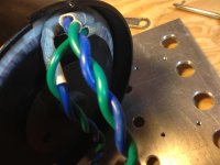
I verified that the new pairing is correct, meaning each new blue/green pair shows very little resistance one to the other (whereas taking a blue from one new pairing and a green from the second new pairing produces infinite resistance).
After 30 seconds the caps seemed to top out their charge at 6.6VDC and the bulb is not dim. Maybe the dim bulb tester is preventing charging? I'm confused😕
After 30 seconds the caps seemed to top out their charge at 6.6VDC and the bulb is not dim. Maybe the dim bulb tester is preventing charging? I'm confused😕
I verified that the new pairing is correct, meaning each new blue/green pair shows very little resistance one to the other (whereas taking a blue from one new pairing and a green from the second new pairing produces infinite resistance).
After 30 seconds the caps seemed to top out their charge at 6.6VDC and the bulb is not dim. Maybe the dim bulb tester is preventing charging? I'm confused😕
you have procedure in #15
- Status
- Not open for further replies.
- Home
- Amplifiers
- Pass Labs
- find the error in this Nelson Pass style PSU, please...