IT is finally time to put my Altec 416's in a box and the title explains it all. I have a rough draft of an idea, but it doesnt seem much lke a TL and more like a BR. would appreciate some help. I am thinking that one of the biggest issues is the overall size, but would like more opinions. I have scanned the MJK site, as well as Brines Acoustics. Cant say have learned any thing, but might as well start somewhere. First try is pretty large and minimally dampened with acoustic fiber . Stuffing it to death fixes a great deal, but i would like to limit this as much as possible.
Attachments
-
 Mathcad - Altec 416 V1-01.png46.1 KB · Views: 511
 -
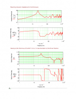 Mathcad - Altec 416 V1-05.png39 KB · Views: 499
 -
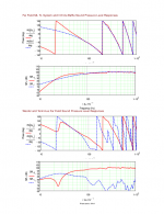 Mathcad - Altec 416 V1-06.png58.5 KB · Views: 484
 -
 Mathcad - Altec 416 V1-07.png23.4 KB · Views: 476
 -
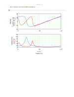
 Mathcad - Altec 416 V1-08.png21.1 KB · Views: 485
 -
 Mathcad - Altec 416 V1-09.png29.1 KB · Views: 128
Have you tried any other alignments like tapering the line? The geometry I was planning for my TD12x drivers was a folded Voigt pipe. The top of the line would start narrow and finish wider. This can be done with single angled divider in a rectangular box. This way you can get a 80" line in a 40" box. More if the "port" runs along the bottom
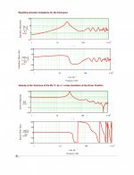
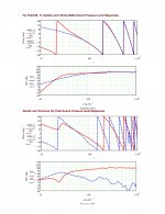
I am still learning to read the MJK sheets. What is the area of the start and finish of the line? 250sq in? (25" x 10")
I have tried all manner of variations. Tapered has its own issues. Based on the Brines site, I think 1:1 is best for low Qts drivers. You must consider room gain in your ultimate design as well.
THe current design is 1:1 with cross section equal to about 2*Sd. It will be folded to make a 39" box, 40 1/2" after plywood. NOw working on version with downward firing port, as I have read this is the most desirable scenario for room interaction and phase issues.
THe current design is 1:1 with cross section equal to about 2*Sd. It will be folded to make a 39" box, 40 1/2" after plywood. NOw working on version with downward firing port, as I have read this is the most desirable scenario for room interaction and phase issues.
It appears sheet listed the port length as 2.5". If you do a down firing port, won't the bottom of the box to floor coupling extend the apparent vent longer than this?
1) Speaker and Room as a System:
Think about running a few room bass gain simulations with your MLTL paper design using a tool like Diffraction & Boundary Simulator 1.20" by Jeff Bagby. This will provide options to adjust port tuning, and perhaps reduce cabinet size by changing the SPL-shape to a higher quarter wave frequency with a "shallow bass shelf" created by long-port tuning that complements the room gain for flat total bass response.
2) If you have a front access screw-in port you can easily adjust lengths, and also make new length adjustments after moving. Stuffing is not an exact science. Bracing volume is difficult to estimate. A 0.5" variation in port length has made a large difference in my MLTLs.
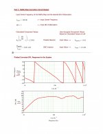
3) So = 25" x 10" A 10" deep cabinet for a 16" woofer may generate too much rear cone reflections for ideal sonics.
3) The MLTL tables I use recommend a much larger So than your posted 25" x 10" I suspect you have also paper-designed other So area sizes which you can revisit, especially if room gain effects are included.
4) A "stylish" bottom port as executed by Jean Hiraga's Altec 604E MLTL might gain home acceptance. OK.. OK... I want someone to figure this out before I build one 🙂
Think about running a few room bass gain simulations with your MLTL paper design using a tool like Diffraction & Boundary Simulator 1.20" by Jeff Bagby. This will provide options to adjust port tuning, and perhaps reduce cabinet size by changing the SPL-shape to a higher quarter wave frequency with a "shallow bass shelf" created by long-port tuning that complements the room gain for flat total bass response.
2) If you have a front access screw-in port you can easily adjust lengths, and also make new length adjustments after moving. Stuffing is not an exact science. Bracing volume is difficult to estimate. A 0.5" variation in port length has made a large difference in my MLTLs.
3) So = 25" x 10" A 10" deep cabinet for a 16" woofer may generate too much rear cone reflections for ideal sonics.
3) The MLTL tables I use recommend a much larger So than your posted 25" x 10" I suspect you have also paper-designed other So area sizes which you can revisit, especially if room gain effects are included.
4) A "stylish" bottom port as executed by Jean Hiraga's Altec 604E MLTL might gain home acceptance. OK.. OK... I want someone to figure this out before I build one 🙂
Attachments

LineSource,
How big is the MLTL you have the graph for?
As for room gain, I have considered it. the MJK sheets have that built in, just takes more info entering. I am trying to decide how much I will get back and how much I will give up with Baffle step loss. Modeling slots is difficult and I have had a few folks elude to the fact they they do not move air in a "fluid" and smoth way. I have an AES paper somewhere showing how much just having roundover ports can affect things like port noise among other things.
Ill post the bigger sibling in a littl e bit. Currently fixing the D^&n dishwasher.
I have strongly considered selling the 288's to buy the 745's for that very reason. Tough, especially considering that Lynn seems to speak just as highy of it as he does the 288. THey will be going into a hybrid JMLC/Iwata and will be directly compared to an IWATA 350.
Last edited:
If you raise and lower the distance from the box to the plinth like the Hiraga design above it will effectively tune the port as well. The cross sectional area will change. Not much harder than trimming a port.
I imagine this is hard to model and is more of a hands on testing type situation. It could get quite expensive, although I like the idea. I had planned to raise the box off the ground about 6" if using bottom firing ports.
Why would it be expensive? Just make some strips if varying thickness to rest the box on and take measurements. Interpolate the ideal and make it permanent.
As you say it is hard to accurately model, especially with a rectangular base. The port is actually a short horn as the CSA is expanding.
As you say it is hard to accurately model, especially with a rectangular base. The port is actually a short horn as the CSA is expanding.
This is how I would do it. I would estimate the virtual port length based on the average distance from the port center to the edge of the plinth. I would add a couple of inches for floor coupling. Then I would calculate the diameter required for this length port in Martins worksheet. I would make the hole at the terminus 2/3 of this value. I would then calculate the height required so that the ring defined by the edge of the hole to the plinth has the same area as the hole. This would be my "probable" spacing. I would then make strips less thick and more thick and test.
LineSource,
How big is the MLTL you have the graph for?
I do not own an Altec or GPA 416-8B. There are several different TS parameters on the web for versions of the 416-8B, which in my TL tables recommend an So from 405 to 437 sq in. I have seen So designs as high as 516 sq in on the Altec Heritage Forum. Using my "personal stuffing method" estimates a quarter wave cabinet height of 52"(17.1" top 32.8%, 34.9" bottom 67.2%) to 54", for a cabinet volume of ~12.5-13 cu ft. A long port can produce a bass shelf which can often complement room gain to extend low bass. Design a clever solution to change port lengths without opening the cabinet. Run a room gain simulation.
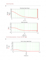
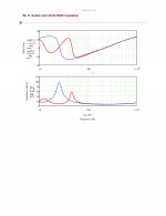
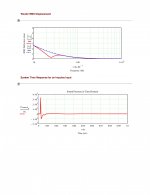
What is more beneficial to quality sound reproduction? Flatter impedance curve, with less than ideal response(like above), or less thsn ideal impedance curve with better response.
Attachments

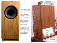
Sad as it may be, The Onken is too large for my wifes liking. I am rearranging the living room already. That took a lot of bribing. I was thinking max width of 24" to 26". Height around 40" to allow for horn mounting on top.
GM would be the best person to ask for the TL and the 416. Modeled as a classic BR, it does not need a huge box, but it does tend to sound better in one.
These efficient, light cone woofers don't react like more recent style woofers.
These efficient, light cone woofers don't react like more recent style woofers.
Ticked him off when I disagreed with him. The above box is about 13^ft. As big as M19. Was going for TL loading over BR, but having trouble deciding what that final curve should look like. On your A7's, is the box tuned to have a peak in the low end to match the increased output of the horn section?
that last one looks good enough for moi
however , you'll have final word by your room
start cutting
edit : she the boss will have final word

however , you'll have final word by your room
start cutting
edit : she the boss will have final word
- Status
- Not open for further replies.
- Home
- Loudspeakers
- Multi-Way
- Final MLTL help