have decided on a simple high and lo-pass passive crossover and L-pad attenuator design (for the tweeter), I have looked on the internet for a wiring diagram that includes all three linked together and can't find one. How do they link up?
Do I connect the positive and negative parts of the two crossovers together at the binding post and add the L-pad closest to the tweeter?
Also, if a resister is rated at 12 watts rms and it is 20 ohm or 1 ohm, how many watts can it handle from the amp before blowing?
Do I connect the positive and negative parts of the two crossovers together at the binding post and add the L-pad closest to the tweeter?
Also, if a resister is rated at 12 watts rms and it is 20 ohm or 1 ohm, how many watts can it handle from the amp before blowing?
Also... sorry to be such noob, but...
I used the tools recommended else where on this site
(http://www.carstereo.com/help/Articles.cfm?id=55#second)
to get the capacitor, resistor, and inductor types. Did I choose wisely?
I used the tools recommended else where on this site
(http://www.carstereo.com/help/Articles.cfm?id=55#second)
to get the capacitor, resistor, and inductor types. Did I choose wisely?
That's the correct way to wire it.
I take issue with the attenuation resistors. No degree of attenuation results in those values.
Also, since this is a textbook crossover which cannot take into account the response curves of the drivers, it will only approximate correctness. A zobel across the woofer will help.
I take issue with the attenuation resistors. No degree of attenuation results in those values.
Also, since this is a textbook crossover which cannot take into account the response curves of the drivers, it will only approximate correctness. A zobel across the woofer will help.
Thanks. and about attenuation...
I know a zoebal requires measurement of inductance and DC resistance of the woofer, but I lack the equipment.
I think I picked a pretty common driver, is their a site that lists that information? Or is their some way to infer it from the impedance graph?
As far as the resistors go, I used the tool at http://www.carstereo.com/help/Articles.cfm?id=55#second and entered in 2 decibels, a figure slightly higher than the sensitivity difference between the speakers. Those are the values it gave me. (driver impedence = 4 ohms, desired attenuation = 2db gave me resistor recommendations which I rounded to the nearest available resistor at speaker city .822 to 1 and 15.44 to 15 ohms. Is that the wrong tool to use?
what resistors would you recommend for a 1.5db difference in tweeter and woofer sensitivity?
Thanks again.
Sorry, my mistake. The 2 resistor values are correct but they are reversed.
As to the parameters on the woofer, see:
http://www.d-s-t.com/vifa/data/mg14sk09-08d.htm
As to the parameters on the woofer, see:
http://www.d-s-t.com/vifa/data/mg14sk09-08d.htm
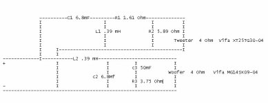
I think I found issue.
Redid calculations. Think attenuator is better now. R1=1.5 OHM, R2=6.0 OHM
Redid calculations. Think attenuator is better now. R1=1.5 OHM, R2=6.0 OHM
Thanks again. 50 mf capacitor?
Using the link you gave me, I found the stats for the FOUR ohm model, I then plugged those (DC resistance 3 Ohms, Voice coil inductance [H] 0.00045)
into the Zoebel circuit calculator (http://www.carstereo.com/help/Articles.cfm?id=55#second) ,
and I get a design using a 3.75 ohm resistor and a 50mF capacitor!
I can't even find 50mF capacitors on speaker city. They only go up to 20!
All coming together now...
Gonna use the .25 ft3 cabinets from partsexpress and install a 2" diam 6.25" long port tuned for 65Hz or so. Only about $440 for parts.
If I can configure it right it should sound at least as good as Totem's or Triangles 4 times the price.
Gonna use the .25 ft3 cabinets from partsexpress and install a 2" diam 6.25" long port tuned for 65Hz or so. Only about $440 for parts.
If I can configure it right it should sound at least as good as Totem's or Triangles 4 times the price.
- Status
- Not open for further replies.
- Home
- Loudspeakers
- Multi-Way
- final crossover schematic