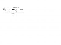
Hello, I posted this question on AA but no answer so far: I discovered that I have digital noise running on the pin 1 wire inside my DAC. I have two questions (see attached picture):
A. Which configuration (1), (2), or (3) do you suggest to filter the digital noise on pin 1? Caps C are 0.01 µF as reccomended.
B. Any suggestion for the tech specs of the ferrite beads to use?
Thanks
Roberto
A. Which configuration (1), (2), or (3) do you suggest to filter the digital noise on pin 1? Caps C are 0.01 µF as reccomended.
B. Any suggestion for the tech specs of the ferrite beads to use?
Thanks
Roberto
Attachments

why not remove the ground wire altogether? its only there for the shield and really I dont see that its needed. I sure dont use it, CMRR is good enough and it reduces the capacitance too. why filter it when you can remove the source of the noise altogether?
Last edited:
Thanks for the reply. I can use Rane notes' suggestion to connect pin 1 to chassis ground, or to avoid to connect pin 1 as you suggested. I tried both but I loose resolution in micro- and macro-dynamics. I tried configuration (3) as suggested by Rane, it is an improvement. So I'm wondering what it is the best configuration. My question is mainly related to the ferrite charateristics, since I can experiment the three configurations.
-Roberto
-Roberto
why not remove the ground wire altogether? its only there for the shield and really I dont see that its needed. I sure dont use it, CMRR is good enough and it reduces the capacitance too. why filter it when you can remove the source of the noise altogether?
It's not "micro- and macro-dynamics" that you hear! It's noise from the mis-wired pin #1. Pin #1 is not part of the signal, it should be connected directly to chassis.
yes, either dont use it at all, or connect it directly to chassis ground. but seriously, if you lose detail from leaving it unconnected, I would have a look at your system, because the level of CMRR should be higher than the level of your hearing. and by leaving it unconnected, I mean completely remove the shield from the cable, otherwise there will be capacitive coupling of the noise it collects; into the signal, as it wont have anywhere else to go if its there but unconnected.
It's not "micro- and macro-dynamics" that you hear! It's noise from the mis-wired pin #1. Pin #1 is not part of the signal, it should be connected directly to chassis.
Hi Kevin,
this a subtle point to discuss. If I do not filter the noise and connect pin 1 straigth without any filtering, you are right. But I experimented solution #3 and it is a sensible improvement in resolution. Whether or not it is due to noise, I like it...
My question is indeed "which are the ferrite specs" you suggest, and also, "which configuration among #1, #2, #3 is preferable". As you can see, having no pin 1 connection or pin 1 connected to the chassis is not listed 🙂 Seriously, I tried them and I like them less... So I want one of #1, #2 or #3, but I do not know which kind of ferrite to choose. This is my actual question, any help is welcome 🙂
Thanks
Roberto
yes, either dont use it at all, or connect it directly to chassis ground. but seriously, if you lose detail from leaving it unconnected, I would have a look at your system, because the level of CMRR should be higher than the level of your hearing. and by leaving it unconnected, I mean completely remove the shield from the cable, otherwise there will be capacitive coupling of the noise it collects; into the signal, as it wont have anywhere else to go if its there but unconnected.
Theoretically speaking, I agree with you. Those were my first experiments. However, practically speaking, I like more connecting pin 1 + filtering.
Just to add some more info, the pin 1 signal I'm considering is coming out from a trasfo connected to the differential output of the AKM4393 DAC chip (plus some resistors). Note that there is no electrical connection between the pin 1 of the trasfo and the chassis ground.
If I connect pin 1 of the XLR connector to the chassis ground (according to Rane notes) or pin 1 of the trasfo to the chassis ground, the sound is not bad but has more grain.
If I do not connect it at all, the sound is dull.
If I connect pin 1 of the XLR connector to the pin 1 of the trasfo, the sound is too bright and edgy.
If I connect pin 1 of the XLR connector to the pin 1 of the trasfo plus use configuration #3 to filter (according to Rane notes and Neutrik EMC ideas), the sound is great to my ears: detailed and clean but not bright. This is why I'm asking advice on this pathway.
Please note that I use active ATC SCM50ASL Pro speakers, and good quality cables, to evaluate the sound (again according to my ears).
Cheers
Roberto
I think that you are just adding another path for noise to sneak into the analog parts of the circuit.
The filtered Neutrik EMC XLR connectors are for analog.
The filtered Neutrik XCC XLR connectors are for digital.
The filtered Neutrik EMC XLR connectors are for analog.
The filtered Neutrik XCC XLR connectors are for digital.
well unless the output needs some kind of bias on the ground line to remove DC offset (not in your case with TX isolation) it is only a shield, has no connection to the output of your dac at all and should only have (indirect) connection to AC/earth ground. for the ferrites, hard to say, the only place I ever use them is on digital lines and they are 600R types, otherwise I use chokes. I wont argue with your findings, as I have had some funny business with cables before and i'm firmly in the for camp, but shield in bal audio is waaay down the bottom of my list after connector plating and dielectric, for balanced audio I never use the shield, because I see no reason to and it just adds capacitance and a path for RF that would otherwise not be there, either directly coupled or capacitively. even with ferrites and resistors you are still allowing ground currents to be at different potentials and they will therefore flow.
so yeah mate, not gonna be much good, I have used 600R FAIR RITE - 2744555576 - FERRITE BEAD, SMD, 6.2mOHM with good results in RCA cables and low noise regulators in AVCC ref supplies for dacs. you could try a choke on the 2 'good' channels too.
good luck
so yeah mate, not gonna be much good, I have used 600R FAIR RITE - 2744555576 - FERRITE BEAD, SMD, 6.2mOHM with good results in RCA cables and low noise regulators in AVCC ref supplies for dacs. you could try a choke on the 2 'good' channels too.
good luck
Last edited:
I see your points. Since I'm experimenting, what if I make a compromise between your suggestions and my proposal? See the attached picture: I connect pin1 of the XLR connector to the chassis ground, and the the pin 1 of the trasfo to the chassis ground, near the trasfo itself and far from the XLR connector.
Thanks
Roberto
Thanks
Roberto
Attachments
I see your points. Since I'm experimenting, what if I make a compromise between your suggestions and my proposal? See the attached picture: I connect pin1 of the XLR connector to the chassis ground, and the the pin 1 of the trasfo to the chassis ground, near the trasfo itself and far from the XLR connector.
Thanks
Roberto
It appears that it is better that I leave both pins #1 floating... Just the two caps connected to the chassis ground, which is meaningless to me... maybe I have an inductive path that causes troubles...
-Roberto
yeah I would look for a source of noise or RF or ground issues elsewhere in your build, where is your star ground for the dac? at the PSU filter caps? or are you including the TX center tap or casing in the star grounding? sure seems like there is funny business going on somewhere. in the occasions I need to, I usually connect any RCA or other SE mode shields, including TX casings to earth ground only through a resistor, caps and back to back diodes as a breaker, but power supply and signal star ground does not get connected at all and is centered at the PSU filter caps after the bridge.
re pin 1 of your TX, if its not the case but the center tap of the traffo secondaries, it should be ignored or used for an RCA shield, no need to connect it to anything if you arent using it for anything signal related, that just provides a link to the secondaries that isnt needed for your diff out purposes.
sorry I cant be of more help
Last edited:
yeah I would look for a source of noise or RF or ground issues elsewhere in your build, where is your star ground for the dac? at the PSU filter caps? or are you including the TX center tap or casing in the star grounding? sure seems like there is funny business going on somewhere. in the occasions I need to, I usually connect any RCA or other SE mode shields, including TX casings to earth ground only through a resistor, caps and back to back diodes as a breaker, but power supply and signal star ground does not get connected at all and is centered at the PSU filter caps after the bridge.
re pin 1 of your TX, if its not the case but the center tap of the traffo secondaries, it should be ignored or used for an RCA shield, no need to connect it to anything if you arent using it for anything signal related, that just provides a link to the secondaries that isnt needed for your diff out purposes.
sorry I cant be of more help
Thanks for helping. I will investigate what's going on. There is probably a bug in the design (it is a modded Behringer SRC2496). I use a USB-to-SPDIF converter and did not galvanically isolate the ground on the USB cable from the computer (but I cut the 5V red wire on the cable). Maybe I should work on that direction.
After experimenting, each configuration had some artifacts in the sound, so the compromise was removing any wire from pin #1 in the trasfo and leaving also pin #1 floating in the XLR connector. So, no connection at all for pin #1, weird, huh 🙂
Bests
Roberto
fancy that 😉 possibly the USB shield is a link for ground loop as well. hard to work with other peoples designs, especially something that is relatively complex WRT ins and outs as the SRC2496.
glad to help, good luck with tracking it down.
glad to help, good luck with tracking it down.
Maybe I found the culprit... I remove the 5V red wire from my USB cable, leaving D+ and D- for the differential transmission and the GND black wire. The latter is actually needed to tell the computer that the USB device is on (the DAC in my case). So, after my computer recognizes the USB DAC, I disconnect also GNS, leaving just D+ and D- for the transmission computer <-> USB DAC. It seems to work indeed...
Cheers
Roberto
Cheers
Roberto
good to hear, yeah not even all dacs will need the ground wire, depends on the receiver and how its set up.
anyway sounds promising, but also sounds like a PITA, perhaps you can rig up a simple switch to lift the ground wire after the handshake is finished
anyway sounds promising, but also sounds like a PITA, perhaps you can rig up a simple switch to lift the ground wire after the handshake is finished
good to hear, yeah not even all dacs will need the ground wire, depends on the receiver and how its set up.
anyway sounds promising, but also sounds like a PITA, perhaps you can rig up a simple switch to lift the ground wire after the handshake is finished
Yap, I actually put a switch on GND (black wire) for that purpose. I'm surprised that it works...
Cheers
Roberto
- Status
- Not open for further replies.
- Home
- Source & Line
- Digital Line Level
- Filtering digital noise on pin 1 of my DAC (XLR balanced)