It depends on how you use the measurements.
The two ways I know are:
1. Take measurements of all of the drivers with the mic in the same position. This is more critical with respect to getting far enough away, also may get trickier with a three way.
2. Take measurements directly on axis with each driver at the same distance (whatever you are using to work out your crossovers you will need to put in the driver offsets.
What I did for my three way setup was to take measurements of the tweeter and M's (MTM configuration) on axis with the tweeter for the high crossover and got that sorted. Later I took measurements mid way between the tweeter of the MTM (MTM playing with the passive crossover) and the woofers (which are in a separate cabinet) for the low crossover design (analog active crossover ). that worked well for me.
30cm is quite close and may not take into account all baffle contributions.
I've explained REW gating before here First crossover, be gentle (saves typing again) 🙂
As per above I did my bass measurements mid way between the woofer and the tweeter of my MTM's your's is TMWW maybe between the M and first W not sure.
Time alignment, not sure. Path lenghts are different from drivers to your ear, I guess ideally all measurements should be taken at the listening distance on the listening axis I've never gone to that trouble and just did the phase alignment based on my 1M distance measurements. I guess this is where option 2 is better (ie measuring each driver and measuring on it's axis) because provided the software you are using is flexible enough you can put in arbitrary listening position and angle and do the calculations based on that.
Tony.
It depends on how you use the measurements.
The two ways I know are:
1. Take measurements of all of the drivers with the mic in the same position. This is more critical with respect to getting far enough away, also may get trickier with a three way.
2. Take measurements directly on axis with each driver at the same distance (whatever you are using to work out your crossovers you will need to put in the driver offsets.
What I did for my three way setup was to take measurements of the tweeter and M's (MTM configuration) on axis with the tweeter for the high crossover and got that sorted. Later I took measurements mid way between the tweeter of the MTM (MTM playing with the passive crossover) and the woofers (which are in a separate cabinet) for the low crossover design (analog active crossover ). that worked well for me.
30cm is quite close and may not take into account all baffle contributions.
I've explained REW gating before here First crossover, be gentle (saves typing again) 🙂
As per above I did my bass measurements mid way between the woofer and the tweeter of my MTM's your's is TMWW maybe between the M and first W not sure.
Time alignment, not sure. Path lenghts are different from drivers to your ear, I guess ideally all measurements should be taken at the listening distance on the listening axis I've never gone to that trouble and just did the phase alignment based on my 1M distance measurements. I guess this is where option 2 is better (ie measuring each driver and measuring on it's axis) because provided the software you are using is flexible enough you can put in arbitrary listening position and angle and do the calculations based on that.
Tony.
Thanks Tony,
Dirac will do the listening position optimization, so I'll align the timing in general.
What do you mean with 1M distance?
Best regards,
Geert
Last edited:
Just one more question.
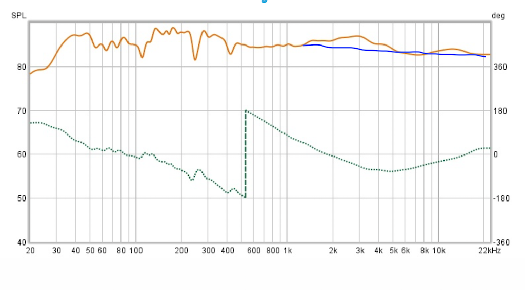
Based on this sweep at 1.5M at tweeter level, I'd say the mid/tweeter range is well aligned.
Sweep: 20191223-Full-Sweep-Finalfrom150cmtweetlevel — imgbb.com
Just the part below 400 Hz seems shaky, but thay could the room and corrected with dirac.
I'm definitely going to time align with inverted polarity and find the sweet spot, but is there any further optimization of the upper frequencies possible?
And what to make of the lower frequencies. Let DIRAC do it?
Yes that definitely looks like room effects to me. What did you do the measurement in? I think some of the previous ones you posted were from REW, the gating will get rid of the room effects (at the expense of the curve being pretty much useless below the gating frequency. In room, you are probably not able to get decent measurements below about 300Hz I would say, unless it is a very big room with high ceilings and you are not doing the measurements at seated level 🙂
A good way of getting an average response in your room is using the moving mic measurement method. see here Moving Mic Measurement It is a bit tricky and you can mess it up by moving too quickly, but once you get the speed and patern down it is pretty useful. Note it is totally useless for phase info though 🙂 just good for getting a more averaged response of your speaker in room.
I think 1.5M in room is going to be tricky to get gated measurements unless there is more than 1.5M to any other object (wall, floor ceiling etc).
Tony.
Measurements were made in my living room. It's a rather small room with walls < 1.5 m.
If I get the chance I'll measure outside someday, but the Netherlands in, January may seem tricky.
Another option is to just let Dirac do the rest from here.
Best,
Geert
If I get the chance I'll measure outside someday, but the Netherlands in, January may seem tricky.
Another option is to just let Dirac do the rest from here.
Best,
Geert
Update 2.
I've measured using gated measurements (3.4 ms was the gating used) for the tweeter/mid crossover. I measured in a 'near' outside place (speaker in window) and as much isolation as I could use.
All measurements were done at tweeter level at 1.00 meter distance.
Flattening of bass: 20200107-flatbasresponse — imgbb.com
Flattening of mid: 20200107-flatmidresponse — imgbb.com (with gating, below 200 Hz not reliable).
Flattening of tweeter: 20200107-flattweeterresponse — imgbb.com (with gating, below 330 Hz not reliable).
Then I designed multiple crossovers of which a Linkwitz Riley of the 4th order at 500 and 1600 Hz as crossovers seemd to give very satisfactory results. I do not have a full explanation of the dip at 200 Hz in the laoyver image.
Crossovers: 20200107-LR45001600 — imgbb.com
Then, I took a full sweep with the tweeter inverted (to see if a dip would arrise at crossover frequency) and if I could increase this dip (gating used at 3.4 ms): 20200107-inverted-tweet — imgbb.com. A 30 us delay on the tweeter resulted in the steepest frequency dip at 1600 Hz.
A full sweep with the tweeter not inverted: https://ibb.co/hsWB8XG, gating used, so anythig below 400 Hz not usable.
A full sweep without gating: https://ibb.co/GkPGhVM.
All in all pretty satisfactory results, and the lower frequencies are maybe due to room effects I still had in the measuring position.
The sound, especially for the higher frequencies, is amazing. The lower frequencies could be further optimized. Either using DIRAC, or by desigining a different crossover.
Any ideas?
To clarify the speaker position: it was on a table in front of a large open window. The floor and the ceiling were thus approximately 1.5 m away from the speaker. The walls (sides) were +/- 2 m away and there was no wall behind.
After some extensive listening it seems the lower frequencies niet some work (too boomy, even for dirac I think) but the higher frequencies worked out superbly.
After some extensive listening it seems the lower frequencies niet some work (too boomy, even for dirac I think) but the higher frequencies worked out superbly.
It looks like you have a room node between 40 and 50 hz.
I'd think about maybe trying to remove that hump between 300 - 450 Hz on the midrange, although there seems to be a hump in this range on your bass measurement too so maybe it's environmental or a measurement issue.
Playing with speaker placement *may* help with the 40-50 hz region, but I have had limited success with a similar peak in my room. You may need to add some eq in to tame that. I suspect it is where your boominess is coming from.
Tony.
How does a 1/3 octave smoothed curve look? That will smooth out a lot of the room effects making the general trend more clear.
The rise between 1 and 3K I'd look at trying to flatten out as well. Generally people go for gentle down slope from bass to treble or the smiley curve (up at bass and up at treble) not usually a hump in the midrange area.
Tony.
The rise between 1 and 3K I'd look at trying to flatten out as well. Generally people go for gentle down slope from bass to treble or the smiley curve (up at bass and up at treble) not usually a hump in the midrange area.
Tony.
And it's final, we're done!
My father in law and I spend a day isolating the innerworks of the speaker and closing all airholes completely (just to be sure) and then we went outside for measuring.
First response was after 6,5 ms so that got me some pretty decent gating for the mid/tweeter part.
Here we go for the results
Flat tweeter: 20201101-Tweetmet-Piet — imgbb.com
Flat mid: 20200112-midflatpiet — imgbb.com
Flat woofer (with filter, did not save flattened response): 20200112-flatwoofermetfilter — imgbb.com.
Since the woofer could be made flat up to about 1100 Hz and the mid down to 350 Hz I chose a 4th order LR filter at 500 Hz. For the tweeter and the mid I chose a 2nd order LR filter in the hopes of a natural sound (not to obvious the sound was coming from the tweeter). I chose 2800 Hz as a crossover since the tweeter was flat up to 700 Hz (almost) and the mid could handle up tot 10KHz. The tweeter was inverted (because of the LR2 filter).
This is the result: 20200107-LR45001600 — imgbb.com
Full sweep: 20200111-fullsweepfinalfilters — imgbb.com.
The result inside was stunning for the mid/tweeter section before DIRAC, with superb clarity (unlike anything I've heard).
I just measured in DIRAC and I am again very impressed with the results of base control. I had a few room nodes which DIRAC filtered out greatly.
That is the end of my project so far.
Hey Tony, that is probably so. I even constructed an extra preset (LR4 at 3500 Hz) since this should result in the best phase result. What is really nice is that DIRAC only needs to correct up to 200-300 Hz and above it the frequency response sort of follows the desired curve already (Screenshot-20200113-214431 — imgbb.com).
I would probably correct the midrange "peak" - maybe the one higher up also. As it is close to the xo maybe its best done with the dirac system?
//
//
Attachments
Last edited:
Yes Dirac covers this very easily.I would probably correct the midrange "peak" - maybe the one higher up also. As it is close to the xo maybe its best done with the dirac system?
//


- Home
- Loudspeakers
- Multi-Way
- Filter recommendation (using Hypex Software Design)