
Some interesting articles regarding switching circuits and EMC....
http://www.diyaudio.com/forums/power-supplies/193705-switcher-emc-design.html
http://www.diyaudio.com/forums/power-supplies/193705-switcher-emc-design.html
We ban discussion of mains-connected amplifiers on this forum... sometimes I think we should put the same sort of ban on filterless amplifiers, especially on removing output filters from amplifiers that ordinarily have them.
If the open loop response of an LC output filter offends you, build a UcD amplifier which puts the filter in the feedback loop of the amplifier and corrects for it.
Filterless amplifiers do exist and have their applications, but they're intended for companies who will put the care/attention into designing a system that meets EMC requirements, and have the capability to test compliance. Secondly, they still do have some amount of filtering, in the form of ferrites and such. TI does give spectrum plots in their app notes showing compliance, but that's for a very specific construction - unless you're building the exact same thing they built, it doesn't apply to you.
Filterless Class D simplifies audio amplifier design | EE Times A lot of info is here .... TNX
Last edited:
You have posted the same link as #43 above!
I would suggest looking at the links from #42 regarding EMC and switcher design.
There is NO such thing as a filterless class D even these low power devices rely on the speaker/headphone coil to act as the inductor, with a couple of caps before.
I have to ask for what reason do you want to build a filterless class D amplifier? Is there some reason or is it due to some myth that it may sound better.....
Last edited:
You have posted the same link as #43 above!
I guess it was just to add the "A lot of info is here .... TNX".
What I think some are missing here is the use of these devices, in small portable electronics, TVs, small PC monitors etc. where the device is pretty much next to the driver (this being the inductor in the filter) or within a certain length (as the not from the double linked TI stuff shows) to limit the antenna effect of the speaker wires and the bandwidth broadcast. Further these devices are designed to be used in the same housing as the driver, allowing further EMC measures to be taken such as shielding to minimise any EMC problems. Being in the same enclosure means that the "switching loops" are within the enclosure and can be shielded, not going out into the open.
Most headphone drivers in small portable devices use headphone amps similar to the one linked to below, again the long headphone wires can act as very good antennas and the length of the cable determines the transmitted bandwidth.
So you ain't going to see a filterless class D driving some long speaker cables to a remote speaker anytime soon, without....
a filter🙂
However, the TPA2000D2 evaluation module passed FCC and CE without any output filter with speaker wire lengths of eight inches and less
The inductor in the filter, or the inductance in the speaker if not using a filter, keeps the change in current low, which decreases the magnetic field in the speaker wires. However, the inductor also acts as an EMI radiator. The electric field, which is a common-mode concern, could be quite large because of the switching voltage if the speaker wires are long enough.
Is there any simple basic example of how two Delta Sigma modulators can be properly synchronized?
Other than clocking them from the same clock source, you can't synchronize two delta-sigma modulators.
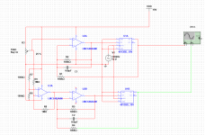
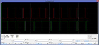
I tried simulation in Multisim 🙁 .... i have some synchronisation but i have small phase shift.I tried D flip flop example.....Op amp is going in to D input through comparator..... I made two Identical circuits with same clock.When one op amp is going "up" and other "down" i have sigma delta output on both but with phase shift.What can couse it?.....Also in relation with modulation depth in one moment there is not synchronisation at all.Thing is that clocked sigma delta depends on clock edge....and that edge is common for two circuits that i have made.So i can have Sigma delta on both to have their centers on exact point all the time i cant achieve.
Soon when modulation starts some delay should be injected in to other clock to have centers aligned (this is what i think-I am asking)....??? .....
Soon when modulation starts some delay should be injected in to other clock to have centers aligned (this is what i think-I am asking)....??? .....
And the fun is getting the clocks to the modulators at the same time...
There are special ICs for distributing clocks, I cant remember any numbers of top of my head...but there may be one that will do what you want. Used them for JTAG clock distribution to several IC's
There are special ICs for distributing clocks, I cant remember any numbers of top of my head...but there may be one that will do what you want. Used them for JTAG clock distribution to several IC's
Last edited:
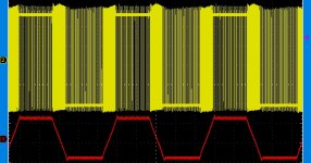
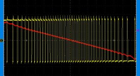
Clock distributor is not the solution.Sigma Delta is changing phase,frequency and duty cycle at same time.Thing is (what i see for now) that it cant be simple clocked.When output start with modulation it has nothing common with clock....This with D flip flop has clock and also phase shift.I tried analog with op amps and flip flops .... its easy to make Sigma Delta output but to inject any synchronisation is impossible without affecting the logic (i tried and sound is affected instantly-I tried 10000000000 combinations and couldnt make it).Does any one here has idea how to synchronize two Sigma Delta PWMs which both related to constant clock look like random pulse generators?Question is how to make centers (not positive or negative edges) of positive parts in puls train to be aligned at any moment.....frequency change is same for same-oposite modulation (when u have 90% and 10% output on two generators frequency is same)....On idle both outputs are on max output frequency and on 50%.How to align centers of both outputs (centers) where outputs has different duty cycles?
You can't align centers of pulses because you don't know what the pulse widths are going to be, you can't see into the future.
- Status
- Not open for further replies.
- Home
- Amplifiers
- Class D
- Filter - less D class amplifier