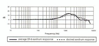
I have the Etymotics ER-6 earphones, which are wonderful but do have a strong peak (12dB) between 600Hz and 6kHz (Etymotics believes is a good thing - "desired response" - but my ears disagree) - see pic below.
I am intending to build a buffered opamp (multi-loop configuration) headphone amp for the ER-6s and wish to include equalisation to remove some of the peak shown in the response graph.
I would be most appreciative a filter design expert could give me some ideas for simple equalisation that could be built into the amp - I am looking for a blunt notch filter that reduces gain by around 5dB at 2400Hz, tapering off to unity by 600Hz on the low side and 6kHz on the high side. In other words to remove approx 40% of the peak in the ER-6 response.
I am assuming some additional RC components in the feedback loop would achieve this relatively simply.
Many thanks in advance
Nic
ps Please note that the x-axis lables in the graph below areincorrect - where 100Hz is shown is actually 200Hz, 1000Hz is actually 2000Hz, etc.
Attachments
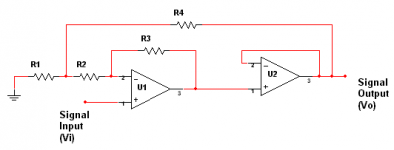
Here is the multi-loop configuration that I refer to above (thanks to Tophu on Headwize.com).
With the resistors numbered as in the diagram below, the output voltage is given by:
<br><pre><br>Vout = Vin * ((R1*(R2+R3+R4)) + (R4*(R2+R3)))<br> ----------------------------------------<br> (R1*(R2+R3+R4)) + (R4*R2)<br></pre><br>
This assumes that U2 is either a unity gain buffer or an opamp configured for unity gain.
Attachments
Harry
Many thanks for your design.
You recommend a separate filter stage - why is this - is it not possible or too complex to combind filter and buffer stage? Note: my gain requirements from the overall amp are minimal (just 2 or 3 x).
By the way, is this a standard filter topology? If so, are there any accompanying formulas, etc.
All the best
Nic
separate filter stage
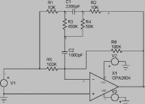
I don't think you could integrate with a gain of 2 circuit very easily. The circuit is based on a resonant equalzer circuit on page 160 of Walt Jungs "Audio IC Op-Applications" Third edition. There are formulas, but I just tweaked one of the examples in the book to your requirements with ICAP/4Students version of ICAP Spice. I used standard capacitor values and played with tuning center frequency and notch depth. 30 minutes of fun, no sweat. This the kind of thing Spice is great for and pretty simple to tweak with without a lot of formulas.
www.intusoft.com
H.H.
Harry
Thanks for Intusoft ref. Please could you post your spice simulation schematic file so I can play too 🙂
Best regards
Nic
Thanks for Intusoft ref. Please could you post your spice simulation schematic file so I can play too 🙂
Best regards
Nic
Spice models
Do you want me to come over and mow your lawn and wash your car also? I gave you a schematic. You can use a generic opamp for the simulation. I thought this forum was called DO IT YOURSELF Audio. Really it is easier too draw the schematic than import a file for a new user. I am just playing with you to maintain my image as the second worst trouble maker on the forum. Want to guess who is the biggest troublemaker? Actually we have our own Spice modeling group at work but they stay pretty busy. For some reason everybody wants spice models.....
Do you want me to come over and mow your lawn and wash your car also? I gave you a schematic. You can use a generic opamp for the simulation. I thought this forum was called DO IT YOURSELF Audio. Really it is easier too draw the schematic than import a file for a new user. I am just playing with you to maintain my image as the second worst trouble maker on the forum. Want to guess who is the biggest troublemaker? Actually we have our own Spice modeling group at work but they stay pretty busy. For some reason everybody wants spice models.....
Attachments

Harry
Thanks for that 🙂
I have been doint some research - gosh this filter stuff is complex - all those Russians: Tchaikovsky, Brezhnev, Gorbachev and a publisher or two: Barnes & Noble, etc. 😀 😀 😀
Best regards
Nix
Thanks for that 🙂
I have been doint some research - gosh this filter stuff is complex - all those Russians: Tchaikovsky, Brezhnev, Gorbachev and a publisher or two: Barnes & Noble, etc. 😀 😀 😀
Best regards
Nix
- Status
- Not open for further replies.
- Home
- Amplifiers
- Solid State
- Filter design request