Thanks for your sharing Euro21.
My friend has done similar research by modeling the filament in Matlab, and simulate the start up process of a 71A about one year ago.
Suppose the material of the wire is tungsten. Using the typical parameters of tungsten, we will get this.


The first section shows the filament temperature rising curve in different power modes. Constant Current, Constant Voltage and Constant Power are concerned. It's the warm up time in different modes.
The later sections show the heat balance process in different power modes. By simulating the heating power and net radiation power, we can understand why there's so much difference in warm up time.

Since the parameters used in the simulation were based on pure tungsten and have been greatly simplified, it's for discussion only.
My friend has done similar research by modeling the filament in Matlab, and simulate the start up process of a 71A about one year ago.
Suppose the material of the wire is tungsten. Using the typical parameters of tungsten, we will get this.
The first section shows the filament temperature rising curve in different power modes. Constant Current, Constant Voltage and Constant Power are concerned. It's the warm up time in different modes.
The later sections show the heat balance process in different power modes. By simulating the heating power and net radiation power, we can understand why there's so much difference in warm up time.
Since the parameters used in the simulation were based on pure tungsten and have been greatly simplified, it's for discussion only.
Thanks to motivations and suggestions from av-trouvaille, I'm trying to turn this design into an available product for diy'ers around the world.
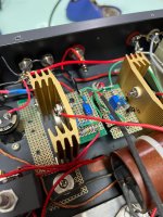
The module has been working in my 300B SE amp for more than 9 monthes. I think it's time to enter the next stage.

Here's the block diagram for the filament constant current source module with automatic adjustment.
The main purpose of building this is to provide a new DHT filament solution which is more friendly to use.
Here're some advantages of this design.
No manual adjustment anymore. The MCU is in charge of adjusting current to maintain filament voltage. Due to the thermal characteristics of filament material, achieving accurate filament voltage by adjusting current is time-consuming. Watching filament voltage gradually changing for minutes after slightly turned the potentiometer is boring but essential. Just let the MCU watching and turning. Now you can plug in tubes and directly turn on the amplifier to listen.
High accuracy. The ADC and DAC section are designed to have high accuracy. The steady filament voltage can be kept within ±0.1% from target value, which can maximize the life span of every power DHT.
Low noise, high impedance with high stability. These are characteristics for good sounding.
Visualized voltage through a RGB LED. The filament voltage status is shown by a single LED. Gradient color from bule to green then to red indicating filament voltage status. A section of optical fiber can be used to lead the light to the front panel of the amplifier.
Delicate aluminium cases. Here're 3D models of the new cases. Cover board isn't shown. The overall dimension when cases are assembled is 140*61*38mm.


If you are familiar with Arduino. I can send the program to everyone who buy this. There'll be more advantages and fun.
Highly configurable. There's only one substance difference between modules for different kind of tubes. That's the shunt resistor value, which determines the maximum current and minimum current adjusting step. All other parameters can be configured either by program or switches on power board. For example, a pair for 300Bs can be easily turned to work with 45, 801A, PX4, PX25, etc. Any kind of tube whose filament current is less than 2.4A and filament voltage less than 25V can be adapted by changing configurable parameters and switches. High current tubes like 845,211,805 and GM-70 can share the same value of shunt resistor, so that simple re-programming and changing of code switch will make it work with another kind of tubes. Higher current version can work with low current tubes, so long as the current adjusting LSB meets the need of achieving certain voltage. Protection limitations are configurable too. Tighter limit can be set to protect precious tubes. The expected maximum current of the present module is about 8A, which is limited by TPS7A4701 + NPN. NJW3281 is the largest BJT with enough HFE that I can find in TO-247. Larger cases will be developed if TO-264 transistors are needed.
Further functions can be developed based on the present hardware. For example, faster start up routine can be achieved by setting a constant voltage start up with higher current limitations. Filament resistance ratio tracking and researching between hot tubes and cold ones can be carried.
Debug can be done by USB to Serial intergrated inside RP2040. If the module works irregular, brief diagnosis can be done by writing program with serial communication enabled. The measured data should be able to tell us some failure possibilities.
Here's a call up to start a small-scale Beta-test. Anyone who's interested in the design, or have puzzles, suggestions and even orders, sending me message or reply to this thread is always welcomed.
I have to say in advance, that the cost of the module is obviously higher than other existing solutions. The price of the module will be high. And I havn't got a chance competing the sound performance of it with other solutions, so the Beta-test seems more like a crowfunding. Contact me if you have interest joining the Beta-test.
The module has been working in my 300B SE amp for more than 9 monthes. I think it's time to enter the next stage.
Here's the block diagram for the filament constant current source module with automatic adjustment.
The main purpose of building this is to provide a new DHT filament solution which is more friendly to use.
Here're some advantages of this design.
No manual adjustment anymore. The MCU is in charge of adjusting current to maintain filament voltage. Due to the thermal characteristics of filament material, achieving accurate filament voltage by adjusting current is time-consuming. Watching filament voltage gradually changing for minutes after slightly turned the potentiometer is boring but essential. Just let the MCU watching and turning. Now you can plug in tubes and directly turn on the amplifier to listen.
High accuracy. The ADC and DAC section are designed to have high accuracy. The steady filament voltage can be kept within ±0.1% from target value, which can maximize the life span of every power DHT.
Low noise, high impedance with high stability. These are characteristics for good sounding.
Visualized voltage through a RGB LED. The filament voltage status is shown by a single LED. Gradient color from bule to green then to red indicating filament voltage status. A section of optical fiber can be used to lead the light to the front panel of the amplifier.
Delicate aluminium cases. Here're 3D models of the new cases. Cover board isn't shown. The overall dimension when cases are assembled is 140*61*38mm.
If you are familiar with Arduino. I can send the program to everyone who buy this. There'll be more advantages and fun.
Highly configurable. There's only one substance difference between modules for different kind of tubes. That's the shunt resistor value, which determines the maximum current and minimum current adjusting step. All other parameters can be configured either by program or switches on power board. For example, a pair for 300Bs can be easily turned to work with 45, 801A, PX4, PX25, etc. Any kind of tube whose filament current is less than 2.4A and filament voltage less than 25V can be adapted by changing configurable parameters and switches. High current tubes like 845,211,805 and GM-70 can share the same value of shunt resistor, so that simple re-programming and changing of code switch will make it work with another kind of tubes. Higher current version can work with low current tubes, so long as the current adjusting LSB meets the need of achieving certain voltage. Protection limitations are configurable too. Tighter limit can be set to protect precious tubes. The expected maximum current of the present module is about 8A, which is limited by TPS7A4701 + NPN. NJW3281 is the largest BJT with enough HFE that I can find in TO-247. Larger cases will be developed if TO-264 transistors are needed.
Further functions can be developed based on the present hardware. For example, faster start up routine can be achieved by setting a constant voltage start up with higher current limitations. Filament resistance ratio tracking and researching between hot tubes and cold ones can be carried.
Debug can be done by USB to Serial intergrated inside RP2040. If the module works irregular, brief diagnosis can be done by writing program with serial communication enabled. The measured data should be able to tell us some failure possibilities.
Here's a call up to start a small-scale Beta-test. Anyone who's interested in the design, or have puzzles, suggestions and even orders, sending me message or reply to this thread is always welcomed.
I have to say in advance, that the cost of the module is obviously higher than other existing solutions. The price of the module will be high. And I havn't got a chance competing the sound performance of it with other solutions, so the Beta-test seems more like a crowfunding. Contact me if you have interest joining the Beta-test.
Last edited:

The module needs two supplies.
One is Raw DC that powers the filament.
The other is Auxiliary AC or DC that powers the control circuit.
The optimum voltage drop of the voltage regulator and CCS is about 4V. It means that Raw DC should be 4V higher than tube heater voltage. Extra voltage drop is needed because Raw DC is variable due to changed AC line input. Ripples from Raw DC should also be considered.
I can build boards with rectifiers and main capacitors as required.
The control board can share the same Raw DC when it's higher than 12V. In this case, auxiliary AC or DC is not needed. If lower interference is preferred or Raw DC is lower than 12V, a 11-20V AC, or 13-32V DC should be connected to the control board for normal operation.


XT60 socket is used for Raw DC input, and XT30 is used for output.
One is Raw DC that powers the filament.
The other is Auxiliary AC or DC that powers the control circuit.
The optimum voltage drop of the voltage regulator and CCS is about 4V. It means that Raw DC should be 4V higher than tube heater voltage. Extra voltage drop is needed because Raw DC is variable due to changed AC line input. Ripples from Raw DC should also be considered.
I can build boards with rectifiers and main capacitors as required.
The control board can share the same Raw DC when it's higher than 12V. In this case, auxiliary AC or DC is not needed. If lower interference is preferred or Raw DC is lower than 12V, a 11-20V AC, or 13-32V DC should be connected to the control board for normal operation.
XT60 socket is used for Raw DC input, and XT30 is used for output.
What I understand the circuit is using a voltage regulator for the filament supply, and the CCS for the cathode bias of the 300B tube.
I believe the design is "overkill".
I used a simple MOSFET (DN2540 type) as CCS for the 45 tube SE. However, the bypass capacitor still required for passing the AC signal. Then, I developed the "Shunt Regulator" for the cathode bias circuit instead of RC and CCS-Capacitor.
A DIY friend in HKG recently modified his 45 amp with the shunt regulator too. He is amazed with the sound quality improvement.
Johnny
Attachments
That's not a cathode bias. It's just a DHT filament supply. The voltage regulator provides stable voltage on the top side, then CCS on the lower side regulates the current through filament. That's a similar topology as V1 to V8 version from Rod Coleman.What I understand the circuit is using a voltage regulator for the filament supply, and the CCS for the cathode bias of the 300B tube.
I think what you're using should be described as constant current self bias, which means replacing the self bias resistor with a 2-terminal CCS. Eliminating all capacitors in signal paths in a SE amplifier is almost impossible, since the power decoupling capacitors are needed in most of situations. And that's not the aim of a filament CCS. A DHT filament CCS is used for guiding signal current to only go through filament. It improves sound quality by avoiding current going through external voltage regulator.I used a simple MOSFET (DN2540 type) as CCS for the 45 tube SE.
Use a Shunt Regulator to replace self bias resistor makes it a fixed bias amplifier.
Different methods of bias can work with different methods driving filament. There's no conflict.
Hi KoitoYuu,
Thanks so much for your clarification. I mis-understood your design. I believe your circuit is kind of filament bias.
The 300B filament current is 1.2A and the cathode voltage is approx 70V. The amount of heat generated from the MOSFET and Rshunt would be 84 watts. Is this correct?
Thanks so much for your clarification. I mis-understood your design. I believe your circuit is kind of filament bias.
The 300B filament current is 1.2A and the cathode voltage is approx 70V. The amount of heat generated from the MOSFET and Rshunt would be 84 watts. Is this correct?
The 300B filament current is 1.2A and the cathode voltage is approx 70V. The amount of heat generated from the MOSFET and Rshunt would be 84 watts. Is this correct?
Let me show you a simplified schematic of filament bias.
I've tested some kind of 300Bs. All of them have a filament current ratings higher than 1.2A.
The CCS using here needs an output capability of 75V 1.25A, which is far beyond the capability of my current design.
The heat dissipates mostly on the resistor. The power MOSFET inside CCS only has to deal with minimum voltage drop and headroom for AC input variation.
You can replace the resistor with a Shunt Voltage Regulator for a lower cathode to ground impedance.
Such a high power dissipation on the resistors makes it unrealistic to use filament bias with power DHTs, not to mention larger ones like 845 or 211.
A couple thoughts for you.
The current consensus is that this kind of regulator will sound better if 1 of the filament legs goes directly to ground.
If so, you can move the CCS to the other side of the filament, change the voltage regulator into a capacitance multiplier/ripple eater, and apply your error correction to the CCS as your final stage. This should improve the sound quality and noise performance quite dramatically.
You can also make an adjustable - temperature compensated - voltage reference. You can set that reference to whatever voltage you like and then use a comparator to set that voltage on the CCS. This would allow you to get rid of the microcontroller altogether.
The voltage regulator side is connected to self bias circuit in my present application. Using CCS side will inlet higher 50Hz noise. I think the voltage regulator output is equivalent to GND. I think the reason why better sound is achieved if one of the filament legs going directly to GND, is that such connection attaches the floated filament supply to amplifier GND tightly. I remember Rod Coleman has said that connect the top side for cathode current is reported to be better in his V8 version.Thcurrent consensus is that this kind of regulator will sound better if 1 of the filament legs goes directly to ground.
Building a high side CCS needs a dramaticly change to my current components selection.
I will try it later as a V5.0 alpha-test when my current design is profitable.
I don't want to get rid of MCUs actually. Such kind of designs have two feedback loop in charge of filament current. One is high speed analog current loop providing a high impedance CCS. The other is low speed voltage control loop providing DC voltage servo. Filters are needed to avoid signals to affect the voltage control loop and cause current to change with signal. The filament voltage will swing with AC cathode current caused by signal. I decided using ADC, MCU and DAC for a digital voltage control loop not only for accuracy and configurable, but also for a better separation between DC voltage and AC signal voltage across the filament. Digital filters can be much better and flexible.You can also make an adjustable - temperature compensated - voltage reference. You can set that reference to whatever voltage you like and then use a comparator to set that voltage on the CCS. This would allow you to get rid of the microcontroller altogether.
Very nice implementation.
I have been working on automatic adjustment current sources too. This is a implementation of the tentlabs approach.
its got slow start, and a LM337 preregulator that tracks the TL431 reference, hence the voltage over the CCS is always 1.25V
The smartest thing in this schematic is the diode clamping of the drive voltage, by choosing the ccs sense resistors appropriately it becomes short circuit proof.
Enjoy
Attachments
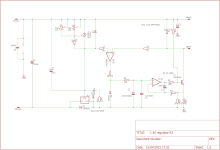
It seems R5 and C2 are used to filter the AC voltage caused by signal current. D3 is a limitation of maximum current. It limits the current within 0.7V/0.68Ω/2≈2A. That's a concise solution. Thanks your sharing. I guess there's slight voltage overshooting when starting.automatic adjustment current sources too. This is a implementation of the tentlabs approach.
So, how does it sounds😏
with the rc values shown there is no overshoot when warming up. ive tested this with a number of DHT's.
That's fine. I also adjust the parameters for a long time to avoid overshoot when warming up.with the rc values shown there is no overshoot when warming up.
I'm working on the V5.1 recently. With some major changes comparing to prevoius versions.
Here's the block diagram of V5.1 and a sample board of V5.0. The V5.0 has a small bug which cause a voltage spike appearing when ADC start and stop.
Buck converters are included for better flexibility. Now you can use transformers with standard output voltage while keeping the chasis cool. For example, a transformer with a secondary of AC18V 3A, which means a Raw DC of about 23V, can be used driving 2A3, 300B, 845/211/805, etc. Any tube whose filament voltage lower than 15V and filament power lower than 40W can be used.
Four buck converters are connected in parallel for 4-Phase interleaved operation, which results in very low ripple and noise at the voltage regulator output. I'll test it and post the results later when V5.1 sample board arrived. The V5.0 has similar level of ripple and noise comparing with linear regulator versions regardless of the spike.
The output voltage of the DCDC is configurable within a specified range. For example from 5V to 14V, or from 13V to 24V.
5V for 2A3, 7V for 300B, 13V for 845, 211 and 805, 24V for GM70.
The current range can be changed by replacing Rshunt, so it can suits most of audio DHTs on order.
Thanks for your post Rod. And thanks for your idea that inspire me to develop the module.
Actually the project was started from just measure the voltage and current of the tube with a single INA226, and show the value on a LCD.
Then I tried to replace the INA226 with INA228. Because I want to use differential input of the ADC to provide higher CMRR when measuring the filament voltage, and the differential input of INA226 has a high input bias.
Now there is a project I for one would buy. A small board with a small LCD one could imbed into the chassis maybe with the lcd pointing out a window in the back. So a person can visually confirm that the voltage and current is ok occasionally. Then just go turn the trimmer a little as the tube ages over time. Then use an affordable Coleman regulator. A fully manual adjustment loop IOW. Might be a nice sister board for Rod's boards.
That aluminum enclosure is sweet though. Looks like a device about to be potted to go up a space capsule.
The previous versions used to have a LCD, but I found that the communication between MCU and LCD is extremely noisy. Running SPI over FPC providing a display at the front is not a good choice in a tube amplifier.A small board with a small LCD one could imbed into the chassis maybe with the lcd pointing out a window in the back.
My current design is a single RGB LED, using the gradient color from blue to green to yellow, then to red to show the relative voltage comparing with settings. The LED is placed on the board, with a optical conductive fibre connected to the front panel.
Last edited:
I think somethink like this will be cheaper and easier to use.Might be a nice sister board for Rod's boards.

LCD or OLED display needs a MCU and ADCs. Such topology is not so far from that of the automatic adjustment version. I think the automatic adjustment version will provide much more enjoyment when using.
Last edited:
I think somethink like this will be cheaper and easier to use.
A linear indicator is of course unsuitable for a power supply controlled by code, because a meter cannot signal the most vital information.
Wherever there is code, the user needs to know one thing above all else ---- Is it crashed?
By long and hallowed tradition, sweeping across all Lands and all Cultures, established and instituted by the great Pharoah William H. Gates III, the state of crashedness must be indicated on a Screen. Any screen will do, so long as it goes BLUE.
Known in ancient times as scutum caeruleum mortis, and in the modern era, throughout all lands as a BSOD, YES, the Blue Screen of Death is an essential component, without which, Customer Services teams cannot function.
I suppose a LED can indicate blue, and although such an acronym as BLOD is evocative, I don't think that it makes the same connection 🙂
I think you misunderstand the function of my RGB LED.I suppose a LED can indicate blue, and although such an acronym as BLOD is evocative, I don't think that it makes the same connection 🙂
Here's the code controlling the LED.
The color of the LED is adjusted according to the measured filament voltage (VFIL) and target filament voltage (Vset).
When VFIL < 0.9 * Vset, the LED is blue, which indicating that the filament hasn't reached the operating voltage.
When 0.9 * Vset < VFIL < 1.0 * Vset, the LED will transit from blue to green, which indicating that the filament reaches normal operation.
When 1.0 * Vset < VFIL < 1.1 * Vset, the LED will transit from green to red, telling users the filament is over voltage and it's time to turn off the amplifier for maintainance.
The color doesn't related to BLOD. It just shows a relative value of filament voltage.
In my understanding, your worry is that you think a reliable evidence indicating whether the system works fine is essential. Like a blinking LED shows the code is running repeatly, the parameters changing on the screen will have similar functions.
I mean using the linear indicator with your module. Instead of developing a digital voltage and current meter with LCD screen working together with your 100% analog filament module.A linear indicator is of course unsuitable for a power supply controlled by code, because a meter cannot signal the most vital information.
Wherever there is code, the user needs to know one thing above all else ---- Is it crashed?
- Home
- Amplifiers
- Tubes / Valves
- Filament CCS for DHTs with automatic adjustment