I am arm wrestling with a stubborn hiss (5mVac measured at speaker terminal). When the driver tube is removed, the hiss is eliminated. I have tried several grid stoppers (1K thru 330K) and none seem to have any effect.
I have tried shielding the tube without any success. Hiss.
I tried replacing the IT with a plate choke Cap/resistor coupling. Still, hiss.
Hiss is certainly coming from the Aa tube. And yes, I am aware that the Aa is not a good match with the 5K IT, but I am just trying to get the feel for the Aa.
Any thoughts?
Attachments
Last edited by a moderator:
Ground the grid. Did the hiss stop? Probably not.
Try a different tube.
Also I assume you don't mean to short the B+ to ground at the 40K resistor...
Try a different tube.
Also I assume you don't mean to short the B+ to ground at the 40K resistor...
Grounding the grid did not help.
I have tried 4 different Aa tubes in both monoblocks. Hiss in both monoblocks for all 4 tubes.
Good catch on the B+ 40K.
I have tried 4 different Aa tubes in both monoblocks. Hiss in both monoblocks for all 4 tubes.
Good catch on the B+ 40K.
Resistor did not help. Tried a battery (-2.6V) filament to ground and this improved to 4mV instead of prior 5mV of hiss. But still, hiss in clearly audible.
OK try reducing the gain of the first stage. Change 300K on grid to 100K. Connect 330k+100nF in series between grid and plate of Aa.
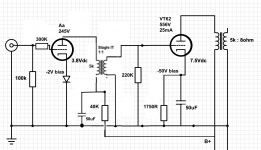
According to the schematic B+ is about 560 V. So the current through the 40K resistor would be (560 - 245) / 40K = 7.9 mA. The anode dissipation of the Aa would than be (245 - 2) x 0.0079 = 1.9 Watt.
According to the datasheet for the Aa the maximum anode dissipation is 1.5 Watt. I don't understand how it could pass 7.9 mA at Vg = -2V and Va = 243 V.
Does the schematic represent the actual situation?
According to the datasheet for the Aa the maximum anode dissipation is 1.5 Watt. I don't understand how it could pass 7.9 mA at Vg = -2V and Va = 243 V.
Does the schematic represent the actual situation?
I think one end of the cathode is at 2V and the other at 5.8V. I guess the diode is a string of diodes to get 2V to ground. Don't think the schematic is very clear. It could be the filament reg is the source of the noise. Certainly would amplify noise from the reg as a grounded grid amp.
Last edited:
If the other end of the filament would be at 5.8 V than it would be even stranger that the Aa is passing 7.9 mA at an anode voltage of about 240 V.
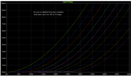
In an earlier thread TS posted these curves for the Aa, which seem to match the datasheet.
In an earlier thread TS posted these curves for the Aa, which seem to match the datasheet.
Attachments
Aa is old type DHT, so filament needs proper DC heating.
Not AC, not SMPS, clean DC (I prefer current)!
Are you read Ale's blog?
Aa DHT Preamp (Part I) – Bartola(R) Valves
p.s.
BTW loading VT82/801a with 5k:8 transformer in A1 region is mistake. Suggested value is rather 10k.
In A2 (zero or positive Volt bias) at lower B+ (for example 300V), with higher current (over 60mA) the proper loading is about 4k.
I think a more detailed schematic is required - there is no indication of the supply used for the Aa heater.
The RCA datasheet for the 801 states that in class A about 45 V AF grid voltage is needed for full power. The Aa has a μ of 30. The interstage transformer has a 1:1 ratio. I don't see how there can be too much gain.
The 300K resistor at the grid of the Aa could contribute to hiss. Why is it there in the first place? A grid stopper could have a much lower value.
I agree with baudouin0. We need a more detailed schematic.
The 300K resistor at the grid of the Aa could contribute to hiss. Why is it there in the first place? A grid stopper could have a much lower value.
I agree with baudouin0. We need a more detailed schematic.
Last edited:
BTW the Aa/Ba (on its own) unable to drive 801a near the A1 limit (0V grid voltage), because the driver tube current is too low (few mA).
801a grid sucks several mA grid current in A2, without proper driver (for example cathode or source follower) unble to drive it.
801a grid sucks several mA grid current in A2, without proper driver (for example cathode or source follower) unble to drive it.
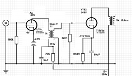
Please find attached a new schematic that reflects some changes to align the operating point of the Aa closer to what Ale has identified. Also, note the LED bias has been replaced with the 2.6V battery. When measuring the filament pins, one of the pins gives -6Vdc, the other that is connected to the battery give -2.6Vdc.
Aa current = (550 - 173) / 70K = 5.4mA
Aa anode dissipation = (169-2.6) * 0.0054 = 0.89W
NOTE: Once the Aa plate voltage was reduced to 169V, the hiss reduced to 3mVac (measured at the speaker terminal). This is barely audible at this point.
Aa current = (550 - 173) / 70K = 5.4mA
Aa anode dissipation = (169-2.6) * 0.0054 = 0.89W
NOTE: Once the Aa plate voltage was reduced to 169V, the hiss reduced to 3mVac (measured at the speaker terminal). This is barely audible at this point.
Attachments
When you look at the curves in post #10 you will see that at Va = 165 V and Ia = 5.4 mA, the bias of the Aa would be positive instead of negative.
The grid of the Aa is at ground potential. In order to get a negative bias, the cathode has to be positive with respect to the grid, so with respect to ground. Therefore you should measure positive voltages with respect to ground on the filament pins of the Aa.
Your measurements show negative voltages at the filament pins (which would mean a positive bias). I assume you did those measurements with respect to ground. I think there's something not right with the way you feed the filaments of the Aa or maybe you reversed the polarity of the battery. But since the filament supply is not shown on your schematic, I can't be more precise.
Last edited:
PFL200 - I am using a TentLabs DC filament supply. These the measurements (ground to filament pins). The difference between the 3 measurements are noted:
Measurement 1:
3.3Vdc filament supply (starved)
Supply feed as-is
Ground-to-filament pin A: -6Vdc
Ground-to-filament pint B: -2.6Vdc
Measurement 2:
3.3Vdc filament supply (starved)
Supply dc feed wires switched/reversed:
Ground-to-filament pin A: +0.7Vdc
Ground-to-filament pint B: -2.6Vdc
Measurement 2:
3.8Vdc filament supply (spec)
Supply dc feed wires switched/reversed:
Ground-to-filament pin A: +1.1Vdc
Ground-to-filament pint B: -2.6Vdc
For each of the 3 measurements, the hiss remains the same (3mVac).
I'm not familiar with the TentLabs DC filament supply.
In your schematic the symbol of the battery indicates that the positive pole is connected to ground. If this is true in reality, than the battery should be reversed.
When you measure, do you have the negative/black probe of your voltmeter connected to ground, and the positive/red probe to the filament pin?
Additional: Your measurements 2 and 3 fit with the battery being connected the wrong way around. So try reversing the battery, while keeping the filament supply connected like it was in measurement 3
Last edited:
I am confident the voltmeter probes are correctly connected.
Measurement 4:
3.8Vdc filament supply (spec)
Supply dc feed wires back to original state (same as Measurement 1):
battery wire are reversed (battery (+) connected to pin A, battery (-) connected to ground).
Ground-to-filament pin A: -1.1Vdc
Ground-to-filament pint B: +2.6Vdc
With this setup, the hiss is down to 2mV which is the lowest I have ever had. It is essentially not audible within 0.5 meter of the speaker.
- Home
- Amplifiers
- Tubes / Valves
- Fighting a stubborn Hiss on Drivers