Hi,
I can't find a direct comparison of the strength of magnets in, for example a ribbon tweeter (~.6 -.8 T usual ((?)) ) to a a.c. signal in the ribbon of only a few volts vs. the field strength exerted on a charged membrane of approx. 4000 V in an electrostat say 2 mm. away from wires spaced at 1/8 inch carrying a a.c. voltage increased by a transformer (X10 ((?)) ).
When considering the input voltage from the transformer (input voltage?) is increased manyfold, and the field charge of the membrane is almost at the ioniaztion of air, :
WHY ARE RIBBON TWEETERS SO MUCH HIGHER IN EFFICIENCY THAN ELECTROSTATICS?
Or, put another way, what is the field strength in Tesla of a (for example) acoustat loudspeaker?
Thanks,
Paul
This is something that I have always wanted to figure out too.
I have found all of the math but never took the time to do the math.
Basically a place to start is to choose what your magnetic field strength will be, as .6t to .8t is fair amount of difference of 1.33 more force.
This is a bit less than the square root of 2 (1.414) or roughly half of double, so this will make a difference of somewhere in between 2db to 4db (2.5db?) in the efficiency just in the two levels of Magnetic Field strength.
I apologize for not being exact and not taking the time to properly work this out.
http://www.sengpielaudio.com/calculator-db.htm
Then you must convert the voltage applied to the ribbon into current, as its magnetic field is directly related to the amount of current flowing in the element.
I have seen this part of the formula in a couple of these threads.
The results well come out as force acted upon the ribbon and typically will be in Newtons or Dynes.
http://www.unitconversion.org//unit_converter/force-ex.html
Then Dynes gets converted to SPL effeciency in db for a given power level.
Then you can do the same for Electrostat's using the proper equations to compare as well.
I think that I had read in Peter walkers papers that this comes out to be around a peak of 50 Dynes per surface area (1 square meter, I think) or so so and the peak force is limited by the ionization, or breakdown voltage, of the surrounding air.
https://books.google.com/books?id=l...Cg#v=onepage&q=peter walker equations&f=false
here is a nicer link,
https://docs.google.com/file/d/0B_l...BkOS00YzI0LTg4NmUtZjFlMGMzMDA1NzY2/edit?pli=1
That is as far as I got, but I hope it helps you to understand a little more.
jer 🙂
Last edited:
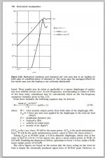
In the book it was stated as 50N/m^2 and not 50 Dyne's as I had stated, sorry for the mis-information.
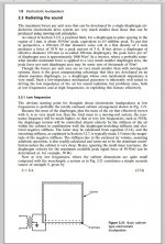
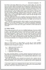
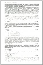
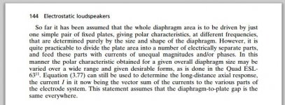
Here excerpts of the pages of that particular section on just the ESL transducer and its forces.
The Magnetic stuff is in the Book as well in another chapter and an even more in depth description in the section before this one..
What an Awesome book it is.
I found those links freely doing a Google search so I hope that there won't be any copyright issues with my post.
jer 🙂
Attachments


Thanks Jer
I guess I'm always trying to reinvent the wheel here, but the gist of my question is about weather you could make a ribbon type speaker with charged plates instead of magnets. So, you would have a high voltage applied to front stators say +5000V and a high voltage applied to the rear stator say -5000V
and a ribbon tweeter hanging in between.
Is this more powerfull, than neodymium magnets to the right and left of a ribbon tweeter.
This was the extent that I would take it,as I was thinking of Acoustat type panels to the sides of these for the midrange and bass.
However, if it is possible to work this arrangement, I would think the best application of this would be on a full range ribbon (a'la Apogee)?
Or maybe I'm way off base here?
Thanks again
Paul
There are some accordion shapes used for planar drivers but the accordion principle is introduced to solve other limitations, not typically because it is a good idea in and of itself.
If you have electrostatic fields, easy enough to shape them over large areas and use flat tight diaphragms to make the sound vibrations without inroducing the complexity and irregularity of accordion shapes.
Ben
If you have electrostatic fields, easy enough to shape them over large areas and use flat tight diaphragms to make the sound vibrations without inroducing the complexity and irregularity of accordion shapes.
Ben
Some of us have been asking about field magnets for cone speakers using electro-magnets, as in days of yore. With contemporary rectifiers and capacitors, a piece of cake to construct now.
When the question was aired a few months ago at DIYaudio, I seem to recall nobody thought you could best a permanent magnet for a cone kind of driver.
Could electro-magnets be feasible for planar drivers????
Ben
When the question was aired a few months ago at DIYaudio, I seem to recall nobody thought you could best a permanent magnet for a cone kind of driver.
Could electro-magnets be feasible for planar drivers????
Ben
In my opinion, no. NdFeBr magnets have flux density @ 15kGauss and electromagnets can not exeed that by much at any current with a soft iron core. Neo magnets are the way to go here. Electrostatic force potential is weak in comparison and highly nonlinear over large excursions.
Though maybe if you were really crafty you could employ both EM/ES drive.
Though maybe if you were really crafty you could employ both EM/ES drive.
Last edited:
I have thought about making a true ribbon ESL, But I don't see the benefit with it.
Complexities can arise do to lack of support of the diaphragm and this will lead into stability issues of it sucking in to one of the stators.
However I think with enough tension it can be done.
I have burned plenty of, and, big enough holes in some of my diaphragm to warrant them practically operating in a true ribbon fashion!!
After a while at the edges of the holes would cause tears, and then, they would start to rattle badly and get worse to the point that I would finally have to replace it.
Also in order to possibly make say a 2 or 3 inch wide true ribbon one would have to use a thicker material in order to maintain enough even tension at only to points (at the ends) and integrity of the diaphragm flatness.
You can forget about using pleats as well, as the surface irregularity's and lack of mechanical stability will cause it to suck into one of the stator's.
IMHO, Because of all this, Using a heavier material you are taking away from the one major benefit of an ESL driver, and that is being able to have the lightest diaphragm in the world only second to a Plasma Driver!! 😉
However I think it would be a interesting experiment just to see how well it would work.
I had actually started a similar design with a 1/2" to 1" ribbon, I routed out 12" long frame out of wood and heavily coated with some Poly but I never finished it.
It wasn't until 2003 when I built my very First panels that I found out exactly what kind of voltage we are dealing with and how to contain them!!!
Even then I had planned on 10Kv to 20kv in my designs and builds but only one set actually made to that range, as most of you already know.
Here is another Genie in a Bottle idea that I have been thinking about, is to use a rather thick piece of Mylar or Acetate or some kind of plastic sheet of say .005" to .020" and suspend it in a frame true ribbon style using a rubber band suspension like the way the Epsilon's are constructed.
This may work good for low to mid frequency's as it would simplify the need of having high strength rigid frame due to the tension needed to make a rigid and uniformly flat diaphragm with thin material.
Put it in a strong HV field and a rather large D/S of say .125" or even a dual diaphragm compounded system.
If such a system could work it would take very little power to drive, maybe even possibly a method from a form Direct Drive !!!
I am for any ideas to get some kind of bass out of them and eliminate the costly and bulky transformer.
jer 🙂
actually the problem is that electrostatic forces are so huge - high enough electric fields to start giving big force on your membrane quickly overcome intervening dielectric's strength, they tear apart the molecules in between in sparks, discharges that then provide a conductive path and let the separated charges get back together
actually the problem is that electrostatic forces are so huge - high enough electric fields to start giving big force on your membrane quickly overcome intervening dielectric's strength, they tear apart the molecules in between in sparks, discharges that then provide a conductive path and let the separated charges get back together
This is something I'm wondering about for a tweeter panel that doesn't need a lot of excursion. I know that in ESL's a smaller d/s distance is good to get more force on the diaphragm. It seems that with a tweeter panel operating above 1-2 kHz one could make the d/s distance really small compared even to a panel operating above 300 Hz. Does ionization start at a lower voltage as the d/s distance goes down? Is there a peak where you don't get any more sensitivity and output as d/s goes down because you have to start reducing bias voltage to prevent ionization? I'm assuming here that the d/s distance is still large enough that the diaphragm isn't physically hitting the stators and is not collapsing to one of the stators due to insufficient tension.
Dan
http://www.ece.rochester.edu/courses/ECE234/MEMS_ESD.pdf
nice calc of E field energy density for air breakdown limited vs 1 T mag field
looks like the spacer surface discharge is a more constraining limit from the graph on the last page
from Paschen's law - Wikipedia, the free encyclopedia
nice calc of E field energy density for air breakdown limited vs 1 T mag field
looks like the spacer surface discharge is a more constraining limit from the graph on the last page
from Paschen's law - Wikipedia, the free encyclopedia
Last edited:
As a physicist I can tell you that the question doesn't make any sense. Electrostatic fields and magnetic fields are different, and you cannot measure electrostatic fields in terms of tesla. But, you can compare the forces that might be generated in a speaker....
Electrostatic loudspeakers work on electrostatic forces - the attraction and repulsion of static electric charges ('static electricity'). There is no magnetic field (of any significance) in an ESL.
Electromagnetic loudspeakers work on magnetic forces, which arise from electric currents.
As someone pointed out earlier, Baxandall shows that the maximum practical acoustic pressure attainable with an electrostatic loudspeaker is about 50 N/m - that is 5 kg force spread over a square metre (limited by dielectric breakdown).
Even a smallish rare earth magnetic is much stronger than this - On Aliexpress I see a 40 mm square magnet that will lift 60 kg, that's about 7,500 x greater force/area. That's why ESLs have to be so much bigger than electromagnetic speakers.
Truly informative to see golfnut's analysis. Thanks.
I'd really like to learn (that is, to have my biases confirmed) as to which system drives the emitting element with the greatest precision. The great magnetic forces of a cone driver are trying to precisely control the heavy weight of a cardboard cone and copper coil. On the other hand, weak electrostatic forces are trying to precisely control a light diaphragm barely more in weight than the surrounding air it is transferring power to.
I'd also like to learn the force (or better, control) concepts of golfnut applied to the behaviour of ribbon drivers.
Thanks.
Ben
Hi Ben
In a conventional driver the electromagnetic motor moves the voice coil (mounted on a cylinder) backwards and forwards. The cylinder is then connected to the cone - so the force pushing the cone backwards and forwards is applied at the base of the cone only. If you think of the cone being slightly rubbery, you can imagine that a sudden movement of the coil will cause the centre of the cone to move, and then a mechanical wave will propagate outwards towards the outside edge of the cone - like ripples when you drop a stone in a pond. Depending on the nature of the cone surround, part of that wave will be reflected back towards the centre of the cone.
This is what happens with conventional drivers. At low frequencies, the cone tends to move as a single rigid piece (hence it is often modelled as a piston). As the frequency increases, the cone movement away from the centre will begin to lag behind, and it will exhibit the mechanical-wave behaviour - so different parts of the cone move in different directions - the cone movement begins to break up - there may even standing waves formed when the reflected waves interact with the primary waves. To supress these resonances, the cone material is normally designed to dissipate energy when it is flexed - paper, amazingly, is a near ideal material.
At very high frequencies, often, only the centre region of the cone moves so that the radiating area of the cone is much reduced. In well designed full range drivers, the whole cone behaves as a piston at low frequencies, and very high frequencies, only the button-shaped dust cap in the centre behaves like a small tweeter.
In between, the cone movement can be a hell of a mess with all of the different bits and pieces moving backwards and forwards at different times. This means that the phase coherence of different frequencies may not be preserved, its sort of OK if this messy behaviour is restricted to the upper audio band because the ear is not very sensitive to phase differences there. Its OK so long as you don't use a large woofer to radiate in the upper vocal range. Instead use a smaller midrange speaker that still behaves as piston at these frequencies.
ESL work quite differently because the whole area of the diaphragm is driven together - the electrostatic force is the same over the whole area- no break up problems and phase coherence is preserved. This is helped by the fact that the mechanical impedance of the diaphragm is almost purely due to the resistive loss as energy is radiated as sound - almost perfect damping - the diaphragm resonances are very heavily damped.
Ribbon speakers, fall somewhere between the two cases. The current through the ribbon is uniform, and so long as the ribbon is in a uniform magnetic field, the force/area of the ribbon will be uniform, just like the ESL. The problem is getting the magnetic field uniform, so the force on the ribbon wont be perfectly uniform.
hope this helps
Rod
you could try reading the link, my words more carefully
communication does require willing cooperation - assuming I mistake E field for mag field units is not willing communication, doesn't include the context of the link or rest of discussion
communication does require willing cooperation - assuming I mistake E field for mag field units is not willing communication, doesn't include the context of the link or rest of discussion
Last edited:
Golfnut -
Many thanks for helpful information. But back to the forces acting on a typical mylar diaphragm versus typical 8-inch mid-range, damping considered secondarily*.
Nobody would be troubled if you simply assumed piston behaviour for present analytic purposes.
Minor point: you earlier mentioned the non-linearity of ESL forces. I thought that shortcoming was adequately analyzed (and dispelled or at least put in perspective) by Hunt's old book recommending two-sided stators and good design.
Ben
*I don't know enough physics to compare the magnet-versus-spider action of a cone driver as compared to the electrostatic-force-versus-air-damping of an ESL in assessing which has more control of the emitting element.
Last edited:
jcx: Sorry to offend, not intended. I was addressing the question posed in the first post on this thread.
Ben: Re linearity of ESLs - yes Hunt's analysis tells us that a push-pull stator arrangement + constant charge operation makes the electrostatic motor linear - but there are many other sources of non-linearity, transformer, non-linear spring constant for the mylar, dielectric absorption... there are quite few, but all minor.
I don't know a lot about conventional speaker design, but I expect that there are at least two main sources of non-linearity - the motor (voice coil+magnet), and I suspect the damping processes in the cone are horribly non-linear, which will affect them once they are operated above the piston range.
Walker argued in his paper on the ESL-63 design that one of the benefits of the ESL is that the model for the ESL transducer was simple - SPL directly related to stator current - with very few undesirable influence effects.
In a conventional speaker, the acoustic output is a very small side effect of shaking the cone about and there are a lot of elements in the mechanism that are non-linear to some degree and can affect the quality of the output. The relationship between input voltage and acoustic output (volume-velocity in this case) is not so simple.
Of course there are good and bad examples of both - I recall seeing a review of a commercial ESL a few years ago that had 8% distortion at full power (it wasn't constant charge)
regards
Rod
Rod - again thanks for good information.snip
In a conventional speaker, the acoustic output is a very small side effect of shaking the cone about... snip
regards
Rod
Funny, for some time I've been saying it makes as much sense to make sound by shaking a heavy piece of cardboard around as it does to power a car with a gasoline engine. The 90-yr old Rice-Kellogg design is primitive.
I now see how you are trying to answer my (ill-formed) question. Earlier, I was trying to ask, "What are the comparable forces on an ESL diaphragm compared to a cone and in relation to the relative weights?" I was thinking that the driver which had the most force or control over each square inch of emitting surface, was the truer driver.
I wonder what would be the right metric for comparing types of drivers. For sure, a "bottom line" such as fidelity on a certain kind of test signal would be meaningful if there could be any kind of agreement about the test stimulus (or what constitutes fidelity). In light of your replies, a basic (perhaps too basic) test signal would be any old sine wave and the metric would be amount of distortion. No doubt there are measurements of this sort and, I am sure, to the credit of ESLs.
Ben
- Status
- Not open for further replies.
- Home
- Loudspeakers
- Planars & Exotics
- field strength of magnets vs. electrostatic