Hi all,
IG's floorstanding FF85WK horns and youtube'd results were pretty outstanding and I am inspired to make a small pair of loudspeakers based on the FF105WK.
Height-wise about 70-75cm. I tried modelling the TQWTL, but sadly the results gave a 66cm high loudspeaker with the driver mounted too far below ear level.
I'm kind of thinking either floorstanding fonken or DBR, but don't known where to start with the design - e.g. internal volumes, port areas and lengths. Can anyone advise?
Cheers,
Andrew
Here's a nice small MLTL that roughly fits the height restriction.
Internal dimensions:
28.5in x 5in x 7.75in (HxWxD).
Zd = 5.625in.
Slot vent full internal width, 1.5in tall at bottom of front baffle. 0.75in long.
Stuff box with uniform density of 0.5lbs ft^3 of Dacron hollow-fibre material & adjust to suit from there. A removable back to allow easy access would be useful -just ensure it's well sealed.
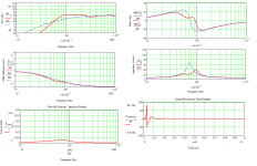
One of my favourite vented alignments -quasi pro-audio style with a little extra broadband gain to help with losses & give a bit more subjective punch to the midbass. Easy impedance load & very linear driver deflection behaviour, both moving toward TL characteristics. It's not tuned for maximum extension, but should strike a useful balance.
Internal dimensions:
28.5in x 5in x 7.75in (HxWxD).
Zd = 5.625in.
Slot vent full internal width, 1.5in tall at bottom of front baffle. 0.75in long.
Stuff box with uniform density of 0.5lbs ft^3 of Dacron hollow-fibre material & adjust to suit from there. A removable back to allow easy access would be useful -just ensure it's well sealed.
One of my favourite vented alignments -quasi pro-audio style with a little extra broadband gain to help with losses & give a bit more subjective punch to the midbass. Easy impedance load & very linear driver deflection behaviour, both moving toward TL characteristics. It's not tuned for maximum extension, but should strike a useful balance.
Attachments
Thanks for the comments on my little FF85WK "BLH" (more of an apex-driven pipe-horn, ah the endless terminology...). It's a neat little box, but could certainly be bettered upon, though I doubt much more punch could be extracted out of this little driver without sacrificing extension or smoothness, areas I feel are already somewhat compromised.
FF105WK and FF125WK have been used in Metronomes by member AmadeusMozart, he like both of them alot.
Scotmoose's design is probably the simplest to build and should sound good IMO. BTW, I assume it's for the FF105WK?
IG
FF105WK and FF125WK have been used in Metronomes by member AmadeusMozart, he like both of them alot.
Scotmoose's design is probably the simplest to build and should sound good IMO. BTW, I assume it's for the FF105WK?
IG
Thanks for the comments, particularly to Scott - for sharing your design (it seems like one of your Pensil designs ") ). Can the driver be positioned near the top?
). Can the driver be positioned near the top?
Thanks for the reply IG81, I'm having to build a pair of low-intensity loudspeakers so that the neighbours don't 'enjoy' my music and I can play more often. BTW, I am also in the process of trying out a tricked-out version of the Velleman K4003. Using upgraded components, an acrylic chassis and home-made heat sink (one rectangular section aluminium inside another). I'll be replacing the psu bypass cap with a PIO bypass cap underneath the board.
I'll be back with updates.
Andrew
). Can the driver be positioned near the top?Thanks for the reply IG81, I'm having to build a pair of low-intensity loudspeakers so that the neighbours don't 'enjoy' my music and I can play more often. BTW, I am also in the process of trying out a tricked-out version of the Velleman K4003. Using upgraded components, an acrylic chassis and home-made heat sink (one rectangular section aluminium inside another). I'll be replacing the psu bypass cap with a PIO bypass cap underneath the board.
I'll be back with updates.
Andrew
(it seems like one of your Pensil designs
Pensils have Mark Audio drivers, these called L'Stylo (thanx Chris)
dave
Thanks for the reply IG81, I'm having to build a pair of low-intensity loudspeakers so that the neighbours don't 'enjoy' my music and I can play more often. BTW, I am also in the process of trying out a tricked-out version of the Velleman K4003. Using upgraded components, an acrylic chassis and home-made heat sink (one rectangular section aluminium inside another). I'll be replacing the psu bypass cap with a PIO bypass cap underneath the board.
It's too bad the K4003 has fixed gain, would have liked to have external resistors to play around. I just find 30db a bit high for the power output, but it's not too bad still. Actually, it might be possible to add a resistor to pin 8, but that'd turn the whole thing into two mono channels the larger the R used, but gain would go down. Can we bridge this amp and use two in this fashion for stereo?
IG
No problem.
The driver is already fairly near the top; it can't be shifted any further up though without impacting on the performance.
Yes, it's akin to the pensils, but not the same as. The alignments are different, although the generalised type is similar.
Hi Scott,
Thanks for the clarification. I won't place then right at the top, will leave about an inch between the frame and interior top.
Cheers,
Andrew
Pensils have Mark Audio drivers, these called L'Stylo (thanx Chris)
dave
Well, since Pensils are generally considered in at least pairs, I was thinking "les"
The tap location is given above under Zd: driver centre = 5.625in from the internal top (which will be about 2in between the internal top & the frame).
Many thanks Scottmoose, I will come back in a few days with the blueprint and woodcuts diagram.
Andrew
I'll be using a logarithmic pot on the input, so that should help - but 30dB does seem like massive gain.
Andrew
I think one could trick the chip by swamping the inernal circuitry with a resistor from the output pins (4 & 6) to pin 8 and from pin 8 a resistor to ground. It checks out in SPICE actually, but feedback from one channel will be entering the other one (vice-versa) and I'd have to do a more extensive sim to evaluate the effects of this. Simply re-using the internal valules (20k and 680R) drops the gain to ~20dB. I would not try this just yet.
IG
FF105WK Le Stylo - Isometric Drawing
Dear all,
As promised I have attached the plans. I have yet to draw the wood cuts. One thing to note, I will be interlocking the front, top, back and base pieces for rigidity and make one side removable until I am happy with the stuffing.
The red squares indicate the interlocking tong & groove, hence the wood cuts of the front and back will be taller than the dimensions shown - to add the tong lengths.
One more question, is the WxD ratio critical? I prefer a wider front with less depth, is this okay providing I reduce the port height to maintain the same port area?
Cheers,
Andrew
Dear all,
As promised I have attached the plans. I have yet to draw the wood cuts. One thing to note, I will be interlocking the front, top, back and base pieces for rigidity and make one side removable until I am happy with the stuffing.
The red squares indicate the interlocking tong & groove, hence the wood cuts of the front and back will be taller than the dimensions shown - to add the tong lengths.
One more question, is the WxD ratio critical? I prefer a wider front with less depth, is this okay providing I reduce the port height to maintain the same port area?
An externally hosted image should be here but it was not working when we last tested it.
Cheers,
Andrew
Last edited:
Okay, here are the wood cuts, in mm and assuming 18mm thick material. I'll be going for 18mm Baltic Birch.
Andrew
An externally hosted image should be here but it was not working when we last tested it.
Andrew
... assuming 18mm thick materialw
When you get your ply. check the actual thickness (in more than one place).
dave
if you'd like the wider / shallower aspect and can live with the vent on the side, why not just mount the drivers on panel C?
5x5 "Russian" Baltic Birch typically runs around 17.5, with the North American domestic 4x8 "Euro / Apple" at 18.5.
After adjusting your cut plan for the actual material thickness, the minor variations from that norm, or of even as much as .5mm across the length / width of a sheet to which Dave refers that we've observed would normally not be much of an issue unless you're planning on dadoes for internal panels, rebates / lock mitres etc around the perimeter, or on designs such as Olson / Nagaoka manifolds
Thanks Dave and Chris for the recommendations, particularly with checking the thickness when routing lock mitres.
By the way, is glueing 10mm thick open cell packing foam along the inside of the top, bottom and back panels a useful alternative approach to stuffing with Dacron? e.g. this:
Andrew
By the way, is glueing 10mm thick open cell packing foam along the inside of the top, bottom and back panels a useful alternative approach to stuffing with Dacron? e.g. this:
An externally hosted image should be here but it was not working when we last tested it.
Andrew
- Status
- This old topic is closed. If you want to reopen this topic, contact a moderator using the "Report Post" button.
- Home
- Loudspeakers
- Full Range
- FF105WK floorstanders