Hello,
I would like to add a music streamer & cd player by plugging a Raspberry Pi 2B in the AVAUX input of my old amplifier Kenwood A-91, via a DAC - probably an I2S one.
In particular, I am looking for a way to unify at least the power on/off function (others such as volume level or source selection would be great additions but I do not have much clues), and I see 3 potential ways of making the RPi interact with the amplifier:
1. 5V relay module: This would enable me to take control of the amp power from RPi GPIO ports. This is probably the best solution in the current state of my knowledge as it seems simple and well documented. I wonder whether such configuration would allow me to use confidently a plugin such as Amplifier Switch (for Volumio). It basically helps to save power by switching off automatically the amp when it detects that no music has been played in Volumio for X seconds (actually milliseconds), and switching it on when it detects that music is being played. Would the additional ON/OFF cycles caused by such feature jeopardise the life expectancy of my already old amp ? I see for instance that the relay I have linked to at the beginning of this point has a MTBF of 100k operations.
2. Kenwood "system control" interface: I also have the Kenwood radio tuner from the same product generation than the amp, and both devices can be linked via the Kenwood "system control" interface. It is actually a male 3,5mm jack to male 3,5mm jack connection, which enables that even when both devices are fed with independent sources of power, when you turn on/off the amp, it turns on/off the radio tuner. What's more, it enables the use of the few buttons dedicated to the tuner on the remote control, the IR receiver being located on the amp.
Linking the amp to the Rpi via this interface could be a neat option but:
a) I don't know how to interact with this proprietary (?) system control interface. I found this hint but I lack knowledge and experience to assess whether and how it could do the trick.
b) I am unsure whether it could allow me to control the amp power from the RPI (instead of the amp controlling the RPI power)
3. The amp includes two female power plug sockets (as per the manual they are supposed to supply up to 200W at 220V, although in my tests I experienced ) I could plug both the Pi & the DAC power supplies there, and when I would turn off the amp, it would turn off the RPi and the DAC. However the control would be from the amp only (less flexible than from the RPi to the amp, but still acceptable to me) and it would trigger a hard shutdown on the RPi which is not recommended as far as I understood (risk of OS data corruption).
Any answers or suggestions would be appreciated.
Best,
dtog
1 - the Amplifier has standby operation. If you can download a schematic and don't mind hacking the amp this would be a low voltage solution - switch high or low from the Pi via a transistor. This is the option I would probably choose.
2 - I assume your option 1 is to switch the mains, either by installing the relay internally to the amp or externally in a separate enclosure. Be sure you can safely build mains equipment before attempting this.
2 - I assume your option 1 is to switch the mains, either by installing the relay internally to the amp or externally in a separate enclosure. Be sure you can safely build mains equipment before attempting this.
Thank you russc for your comment.
Indeed, my option 1 was to place a relay within the amp box (somewhere in the green square of below picture) to switch the mains (highlighted in red in the picture).

Do I understand correctly that the use of a transistor would have two advantages over my option 1:
- beneficial to the amp longevity by switching on/off from/to the standby mode (instead of main power supply);
- reduce safety risks by avoiding manipulations (although quite simple) in higher voltage circuitry ?
It would be one of my first electronic project but it sounds instructive, and moreover it seems that I may be able to control the amp volume from the Pi as well that way. However I do not get its logic yet - where should the transistor be located? between the Pi and the amp? Within the amp ?
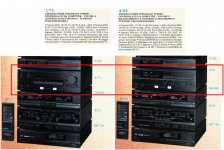
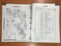
I could find the service manual of the A-71, which is from the same product generation than my A-91 amp but with less power and a few functionalities left to the A-91 (I attach to this post a photo/spec comparison between A-71 & A-91, one page of A-91 Service manual found on eBay, and a temporary link to A-71 Service Manual originally found at hifiengine.com). It includes some detailed schematics of the circuitry.
I may actually be able to purchase the one for A-91, but I wonder what would be the next step and what I should be looking for in it on the basis of the A-71 as I don't have a clear view for now.
Indeed, my option 1 was to place a relay within the amp box (somewhere in the green square of below picture) to switch the mains (highlighted in red in the picture).
Do I understand correctly that the use of a transistor would have two advantages over my option 1:
- beneficial to the amp longevity by switching on/off from/to the standby mode (instead of main power supply);
- reduce safety risks by avoiding manipulations (although quite simple) in higher voltage circuitry ?
It would be one of my first electronic project but it sounds instructive, and moreover it seems that I may be able to control the amp volume from the Pi as well that way. However I do not get its logic yet - where should the transistor be located? between the Pi and the amp? Within the amp ?
I could find the service manual of the A-71, which is from the same product generation than my A-91 amp but with less power and a few functionalities left to the A-91 (I attach to this post a photo/spec comparison between A-71 & A-91, one page of A-91 Service manual found on eBay, and a temporary link to A-71 Service Manual originally found at hifiengine.com). It includes some detailed schematics of the circuitry.
I may actually be able to purchase the one for A-91, but I wonder what would be the next step and what I should be looking for in it on the basis of the A-71 as I don't have a clear view for now.
Attachments
Thank you for your input, synonymous.
I guess this would indeed solve the main issue I raised with my option 3 and would allow the RPi and the DAC to shut down smoothly to prevent SD card data corruption when turning off the amp.
So I keep this in mind, while digging further the option 1, as if possible I'd rather have the RPi controlling the amp (power button and if possible volume level).
That's actually my page and video of a project that I put together. My current project is highly based on that foundation but yet has some differences. I use shairport-sync which runs headless and is operated by other remote devices, like phone, computer etc... Being simple, I actually run it as read only so that there's no issues of corruption of the SD and the power can be pulled out or lost in any ways. This system is all under one hood with the amp and raspberry pi, however I do plan to produce a standalone DAC that will do everything you see in that previous video, including a power connect for control of an amplifier or other.. I am in the final stages of developing my amp receiver, then it will also be the platform from which I simply delete the amplifier section and use as a standalone DAC. I will be using the diy chassis for it and it will be a quality unit with it's own power for the pi and DAC outfits (exchangeable). And as I said, will have a control relay of some kind for aux equipment. Rather than as in the video where I used gpio to control the tracks etc, I expect users to use another method like USB or other multimedia keyboard. These devices, like my current project, don't need a power switch on the faceplate because they're designed to stay on and control the amp itself. There's some additional functionality and LED indicator....
Check out this video... But imagine it as a standalone DAC for purposes like your own..
My prototype..
YouTube
Check out this video... But imagine it as a standalone DAC for purposes like your own..
My prototype..
YouTube
So if I understood correctly in this future project, you plan to link the amp power via a relay?
In that way when the RPi wants the amp to poweroff it would switch the amp status from power on => power off without going through standby mode, right? I wonder whether this could have an impact on the longevity of the amp..
Have you thought of a way to control the volume of the amp via the RPi (i.e. the action you perform manually in your previous sUpPi video at 7mn48)?
- Home
- Design & Build
- Construction Tips
- Few questions about interfacing of my amplifier with a Raspberry Pi streamer