I am looking for FET switches for some old vintage gear---specifically called for on the schematic are N-channel FETs (2SK105J or 2SK117BL or 2SK362BL) and P-channel FETs (2SJ74BL or 2SJ104). These are all obsolete and no longer available. I don't think it is HIGHLY crucial that a replacement be exact---these are for switching in & out pots for equalization---as long as they are low in distortion, high off-resistance and low on-resistance. Any suggestions?
sourced 2SK49 and 2SK193 for a vintage reel player from the local market although the guy charged me an arm and a leg.
But I can check from the local market, a guy who is operating the shop since 60s may have them but I am not sure of the price.
But I can check from the local market, a guy who is operating the shop since 60s may have them but I am not sure of the price.
Thanks for the replies. I found this N-channel:
https://www.mouser.com/datasheet/2/308/MMBFJ113_D-1811481.pdf
which looks like it will work; only 30 ohms on-resistance. In my research, it seems that N-channel devices have much lower and more linear on-resistances than P-channel ones. Therefore I think I will just use those and use a simple 2N3904 to invert the logic when needed.
However, I can't seem to get an NFET to work as a switch in LT Spice XVII. I've attached a .pdf example of what I am trying to do---simply turn on one path and turn off the other by changing the gate voltage from positive to negative. What am I doing wrong here?
Attachments
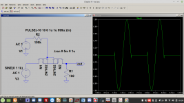
...get an NFET to work as a switch...example of what I am trying to do---.....
I see Q2 with 30 Volts base-emitter. A real device will just melt.
Attachments
Aah, to hell with the FETs! More trouble than they're worth! I found a way to switch that has near-zero ON resistance and distortion, megohm off resistance, and fits in the same space as the four TO-92s. It's called a RELAY! If I were making 10,000 of these boards, it wouldn't be economical; but for a few methinks it's a better solution.
Nowadays there is no need to call for JFETs. Easy available MOSFETs will do as well.
LH1540 solid state relay looks like that
Sorry but your circuit makes no sense, no surprise simulation software spits it out.
And even if it worked, WHAT are you trying to switch?
There is only ONE generator AC1 , ONE load R4, which will always be connected, either through J6 OR J3 in series with J2 (and why use 2 in series?)
And where is switching voltage applied?
Your schematic shows neither control switches nor waveforms nor external jacks.
Unless you define that, a relay switcher won´t work either.
Hmmm...the LH1540 might do the trick, but two 1540s are still too big----I need DPDT. Is there a solid state relay that does that in 15mm x 7.5mm footprint?
Yeah, my drawing by itself doesn't make much sense, does it! Sorry, I was trying to be as terse as possible. I have a three-pole multiple-feedback bandpass filter that I need to switch in and out of the circuit with an existing control voltage that goes from +15 v (for bypass) to -15v (circuit in line). In bypass, the circuit must not be seen as any type of load either as a load or source impedance.
- Home
- Design & Build
- Parts
- FET switches