Hi Marc,
Very artistic! My wife even liked them!🙂
😎
@ LC, AWW! I'm looking forward to your report on the sound quality!
hehe Harry, they never stopped to surprise us

Yes artistic experimental work, that's what I like the most in our DIY activities.

P.S. How's your VSSA standing?

Last edited:
Idefixes
That is really impressive work.
For next 2 weeks I am away for holidays so I have restricted internet acces but I am looking forward to see the complete result.
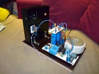
It will take a little more time, i am always waiting Sanken and VAS devices. BG1_bjt will run on the +/-36V test chassis (sheet of wood with complete power supply, soft-start, DC-speaker protection). I just have to swap heatsink who has amp-board on and to connect supply to make it running. I will take few picture tomorrow.
Final building wil integrate PMI capacitance multiplier and monobloc configuration.
Marc
Last edited:

hehe Harry, they never stopped to surprise us
Yes artistic experimental work, that's what I like the most in our DIY activities.
P.S. How's your VSSA standing?
That's for me the better "engine" for diy....If i say you that i have no more fun in getting together your VSSA module....all work is done....For sure do the expect result i'll do it...but for sure too if result is as magic as i read....i will build my diy single layer ALF16NP05 layout...It's waiting frendly in my computer for printer outpout.....and waiting Farnell availability....
Marc
Last edited:
@LC, I agree with you fully!😉
I am waiting for the capacitors and PSU's parts to arrive next week, I hope. Then, i will be ready to finally start building my VSSA.
😎
I am waiting for the capacitors and PSU's parts to arrive next week, I hope. Then, i will be ready to finally start building my VSSA.
😎

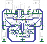
I think some of your track need to take thickness, as caps dedicated to power output needed to be a bunch nearer to Hexfet...
Marc
Marc
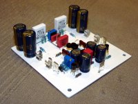
If you are going to use caps next to the o/p transistors put them as close as possible to o/p devices anyway (example bellow).
For one pair of hexfets I didnt used any source resistors ( i know that the are recommended) and results were perfect.
I have measured DF of latfet version and at 8R 100Hz it was 735 so I think is very good.
After I come back from my holidays I will try to mesure BJT and FET-hex version too
For one pair of hexfets I didnt used any source resistors ( i know that the are recommended) and results were perfect.
I have measured DF of latfet version and at 8R 100Hz it was 735 so I think is very good.
After I come back from my holidays I will try to mesure BJT and FET-hex version too
Attachments
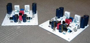
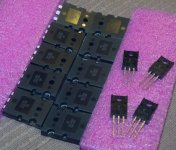
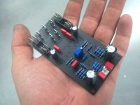
Yesterday night i populate second board. I still waiting for driver and Sanken output. I just take a look at my stock in case they take more time to than i expected. I have some 2sc4793/2sa1837 from other project, MJL4281/4302, NJW3281/1302, and MJL3281/1302... to begin with...
Marc
Marc
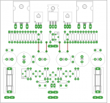
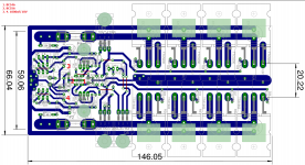
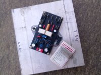
My PCB version VSSA BJT, double sided without metallization:
Not tested, it will be soon.
An externally hosted image should be here but it was not working when we last tested it.
Not tested, it will be soon.
Looks like a very good component placement, but the grey-on-grey layout is hard to see. Looking forward to more pics... 😀My PCB version VSSA BJT, double sided without metallization...
Yesterday night i populate second board. I still waiting for driver and Sanken output. I just take a look at my stock in case they take more time to than i expected. I have some 2sc4793/2sa1837 from other project, MJL4281/4302, NJW3281/1302, and MJL3281/1302... to begin with...
Marc
MJL4281/4302 one of the best ON Semi BJT, I used those and other MJL or MJW but these are my favorite.🙂
It would be good to know how will measure up with the Sankens.
Greetings G
MJL4281/4302 one of the best ON Semi BJT, I used those and other MJL or MJW but these are my favorite.🙂
It would be good to know how will measure up with the Sankens.
Greetings G
I have five each...If sanken take too long time maybe will i try with these since i have no projet on them.
Marc
Attachments
Last edited:
Yes, I know 😀 . I did it because the PCB is not been tested. But I can change the color of the lines if u want.Looks like a very good component placement, but the grey-on-grey layout is hard to see. Looking forward to more pics... 😀
BR
That's a work of art, Marc! If I could do that, I might not bother having them "professionally" made...🙂
That's a work of art, Marc! If I could do that, I might not bother having them "professionally" made...🙂
Hi Pete,
"having them pofessionnaly made" has some advantages...I really hate the drilling PCB session for exemple...or having metallized drill made under PCB transistor soldering easyer.....but desoldering not....
Marc
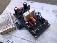
VSSA with IRF640/9640 on a small PCB
Really neat job...Why the output coil? have you encounter issue with stability?
IRF640/9640 => Headphone amp???
Marc
- Home
- Amplifiers
- Solid State
- FET-hex explendit amplifier