Think I've wrapped up optimizing this newest amplifier for using TMC (selectable via a jumper plug). The results are most rewarding. I settled on C1 = 120pF, C2 = 680pF and R = 1K.
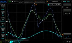
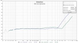
I tested R = 680ohms and found no measurable difference in THD sweeps at 1W, 5W or 45W into 8 or 4 ohms. I could see a small difference in the crossover glitch on the output from the HP334A distortion analyzer (scope picture below).
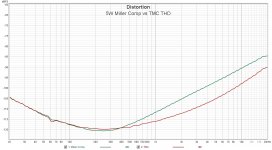
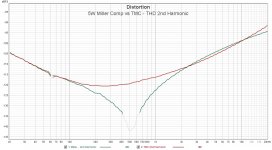
TMC clearly knocks down THD odd harmonics by an impressive amount without much or any penalty in overall THD reduction across the audio band IF the values of C1 and C2 are chosen properly. The value of R (1k or 680) did not make a difference. I did not pursue a smaller value of R.
Scope picture of crossover distortion - distortion residue output from HP334A
Blue - regular Miller compensation, Green - TMC with R=1k, White - TMC with R = 680ohm
I tested R = 680ohms and found no measurable difference in THD sweeps at 1W, 5W or 45W into 8 or 4 ohms. I could see a small difference in the crossover glitch on the output from the HP334A distortion analyzer (scope picture below).
TMC clearly knocks down THD odd harmonics by an impressive amount without much or any penalty in overall THD reduction across the audio band IF the values of C1 and C2 are chosen properly. The value of R (1k or 680) did not make a difference. I did not pursue a smaller value of R.
Scope picture of crossover distortion - distortion residue output from HP334A
Blue - regular Miller compensation, Green - TMC with R=1k, White - TMC with R = 680ohm
Attachments

mikebeth,
Practically, you choose C1 as you would for Miller compensation - from the LTP transconductance and desired bandwidth - then add C2 of twice or so the capacitance, then find the minimum value of R which keep the amplifier stable. I don't see your LTP in the schematic clip you posted, but guessing you are using Self's usual 6mA tail current source, 120pF sounds like an awful lot. With it, you are getting about 40dB loop gain at 20kHz, which is only 10dB better than with a typical Miller compensation. Try C1=33pF or 47pF - it would leave you more loop gain and reduce distortion further. C2 would then be 68-100pF. R will probably need to be increased.
Practically, you choose C1 as you would for Miller compensation - from the LTP transconductance and desired bandwidth - then add C2 of twice or so the capacitance, then find the minimum value of R which keep the amplifier stable. I don't see your LTP in the schematic clip you posted, but guessing you are using Self's usual 6mA tail current source, 120pF sounds like an awful lot. With it, you are getting about 40dB loop gain at 20kHz, which is only 10dB better than with a typical Miller compensation. Try C1=33pF or 47pF - it would leave you more loop gain and reduce distortion further. C2 would then be 68-100pF. R will probably need to be increased.
Last edited:
mikebeth,
Practically, you choose C1 as you would for Miller compensation - from the LTP transconductance and desired bandwidth - then add C2 of twice or so the capacitance, then find the minimum value of R which keep the amplifier stable. I don't see your LTP in the schematic clip you posted, but guessing you are using Self's usual 6mA tail current source, 120pF sounds like an awful lot. With it, you are getting about 40dB loop gain at 20kHz, which is only 10dB better than with a typical Miller compensation. Try C1=33pF or 47pF - it would leave you more loop gain and reduce distortion further. C2 would then be 68-100pF. R will probably need to be increased.
Correct, I am using 6mA of tail current. I had planned for a conservative 100pF compensation, partly because of the output devices and connections they employed.
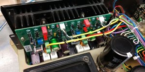
This is a replacement amplifier board for an old Pioneer SX-750 receiver (my personal receiver). It uses TO-3 output devices connected by ~10cm wire leads. I have changed the output devices to more recent MJ21193/4 transistors, but their fT is only on the order of 4~5MHz. And the wire connection leads make me concerned about parasitic oscillations, thus my conservative compensation values. Thoughts?
(Other than "why are you modifying an old Pioneer reciever?". LOL)
Should not be a problem - output transistors connected by wire leads work fine in amplifiers with bandwidth in low single MHz, which should be plenty for a two-pole compensated amp. Just twist the wire leads to each output transistor, so that the magnetic fields produced by the collector and emitter currents cancel each other.
For example, a typical amp from Self's book has a 100pF Miller compensation, 700kHz bandwidth and 30dB of loop gain at 20kHz. If you keep Miller but drop the capacitance to 47pF, you get 1.5MHz (should be still safe for stability with wire leads) and 37dB, not a huge improvement. If you use two-pole with, say C1=68pF, C2=220pF, R=4.7k, you get 1.4MHz bandwidth, which is just as safe, and ~50dB at 20kHz, a 20dB/10 times improvement in distortion.
For example, a typical amp from Self's book has a 100pF Miller compensation, 700kHz bandwidth and 30dB of loop gain at 20kHz. If you keep Miller but drop the capacitance to 47pF, you get 1.5MHz (should be still safe for stability with wire leads) and 37dB, not a huge improvement. If you use two-pole with, say C1=68pF, C2=220pF, R=4.7k, you get 1.4MHz bandwidth, which is just as safe, and ~50dB at 20kHz, a 20dB/10 times improvement in distortion.
If you use two-pole with, say C1=68pF, C2=220pF, R=4.7k, you get 1.4MHz bandwidth, which is just as safe, and ~50dB at 20kHz, a 20dB/10 times improvement in distortion.
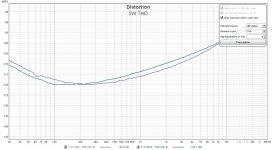
Sounds reasonable. I am taking measurements now with C1=68pF, C2=330pF, R=1k. Results so far are mixed. Lower frequency distortion is a little higher, 3rd order THD above 10kHz is pushed down well. Basically the high frequency corner for 3rd is moved up in frequency
What is your thinking regarding the reason to possibly increase R ?
Attachments
It may be needed for stability. The value of R affects the phase margin of the amplifier, and with low R, that phase margin may be insufficient. Other than that, I see no reason for increasing it.What is your thinking regarding the reason to possibly increase R ?
Makes sense. I am puzzled why decreasing the TMC capacitor values (while retaining their ratio at about 5X) resulted in a increase in distortion at frequencies below 10kHz. The decrease in distortion above 10kHz was seen as expected.
Clearly lower values of compensation capacitors should produce more open loop feedback. I could see that clearly when SPICE simulating the open loop feedback of TMC. The results surprised me. Most likely there is another effect with the smaller capacitors taking place that is producing an offsetting increase in distortion.
Clearly lower values of compensation capacitors should produce more open loop feedback. I could see that clearly when SPICE simulating the open loop feedback of TMC. The results surprised me. Most likely there is another effect with the smaller capacitors taking place that is producing an offsetting increase in distortion.
Miller cap acting as local FB linearizing the VAS transistor maybe? Not sure how low in frequency this would have an effect though.
One possibility is that the local feedback via the compensation network lowers the input impedance of the second stage, decreasing the amplitude at the collectors of Q1 and Q5, stabilizing their operating points and thus improving linearity. If this hypothesis is correct, than the more local feedback you have (e.g. higher capacitance and/or higher frequency), the more pronounced the effect would be. Cascoding the LTP would solve the issue.
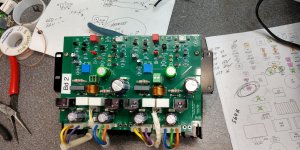
Thanks for all the help wrapping this project up Alex (and others). I buttoned it up today and put the receiver (vintage Pioneer SX-750) back in service in our kitchen. Sounds great playing Dire Straits 🙂
Attachments
- Home
- Amplifiers
- Solid State
- Feedback: Two pole vs. output inclusive ?