Happy Holidays all! 
Does anyone have any experience with different advanced solid-state amplifier feedback methods - specifically two pole compensation vs. output inclusive compensation (as D.Self refers to it)?
I am currently evaluating the performance of having added output inclusive compensation (switchable via jumper: conventional or output inclusive) to my latest amplifier PCB build (ver3) and am quite impressed so far at how it reduces crossover distortion. I had considered designing the amp with 3 selectable feedback methods (conventional, output inclusive or two pole), but got lazy during the PCB layout and left out the two-pole option. I judged that the output inclusive compensation would more effectively combat crossover distortion, as other distortions in the previous PCB (ver 2.1) had been pushed below 0.001%. Now I wish I had included two-pole as an option for evaluation purposes.
I'd be interested to hear about/discuss/share anyone's findings in this design area. Currently I'm determining the optimal bias setting for both compensation methods and then will begin gathering performance graphs, etc.
Mike
You can very easily arrange to jumper the feedback options in an amp to provide TPC, TMC or Miller.
TPC and TMC both offer up to 20 dB more feedback at 20 kHz and a concomitant reduction in distortion. TPC does carry a small overshoot penalty, but you can compensate for this by adjusting the input filter cut-off frequency, or using Cordells’s ‘bridged T’ technique - but you will sacrifice a few dB distortion performance going down that route. TMC does not carry an overshoot penalty.
Here’s an amp that allows different feedback schemes to be selected Ovation e-Amp: A 180 Watt Class AB VFA Featuring Ultra Low Distortion (see page 42 onwards in the download for the compensation design)
Last edited:
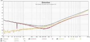
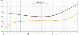
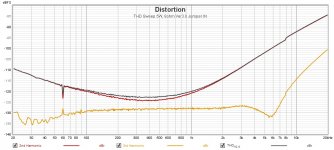
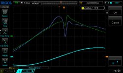
Finally got to run performance measurements on an amp channel on the new PCB. The impact that TMC has on the size of the crossover distortion (visible as distortion residue from my HP334A distortion analyzer) is impressive. It shrinks the size of the crossover 'glitch' by a factor of 2 or 3 easily.
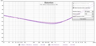
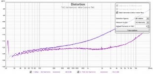
The resulting THD sweeps are interesting. Selecting TMC as opposed to conventional compensation lowers the odd order harmonics at the higher frequencies impressively at the expensive of increased even order harmonics overall.
The deep dips in various THD sweeps at 3, 4 or 6kHz are interesting and bear some looking into.
Attachments
-
 THD Sweep 1W 8ohm Jumper OUT.jpg163.2 KB · Views: 382
 -
 THD Sweep 1W 8ohm Jumper IN.jpg156.3 KB · Views: 375
 -
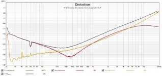 THD Sweep 5W 8ohm Jumper OUT.jpg161.4 KB · Views: 373
 -
 THD Sweep 5W 8ohm Jumper IN.jpg157.6 KB · Views: 367
 -
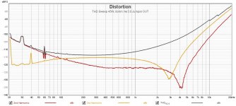 THD Sweep 45W 8ohm Jumper OUT.jpg161 KB · Views: 375
 -
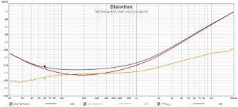 THD Sweep 45W 8ohm Jumper IN.jpg152.9 KB · Views: 103
Last edited:
Difference in magnitude of crossover "glitch" between TMC (green trace) and conventional compensation (blue trace). Still wish I had designed in a jumper to allow for two-pole compensation in addition to TMC and conventional for direct performance comparisons.
Perhaps if I have a version 3.1 board made. PCB fab & delivery from China is amazingly fast and relatively cheap these days.
Perhaps if I have a version 3.1 board made. PCB fab & delivery from China is amazingly fast and relatively cheap these days.
Attachments
"Selecting TMC as opposed to conventional compensation lowers the odd order harmonics at the higher frequencies impressively at the expensive of increased even order harmonics overall."
Yes, perhaps the best solution is an intermediate compensation, a mix of conventional and TMC : try it !
Yes, perhaps the best solution is an intermediate compensation, a mix of conventional and TMC : try it !
I'm circling back to review what Cordell and Self have to say about TMC in their respective books before looking at how to possibly tweak the values and setup for TMC that I'm using.
I have currently a fairly conservative level of compensation (two 220pF caps in the TMC configuration which converts to 110pF conventional comp. with the jumper removed)
Nicely the amp does not break into instability when the jumper is removed or installed even at full power with a 10kHz signal into 8ohm dummy load. I had my finger on the power switch the first time I tried that - still not sure it's a great idea to provoke an amp like that. But curiosity won out!
Also I was surprised at the effect that PCB layout had on the performance. Going to version 3.0 from version 2.1 I totally reworked the PCB layout (shamelessly picking up ideas from looking at the layout of D.Self's "Blameless Amplifier" PCB's)
The THD sweeps all improved by ~ 10dB at all frequencies for the same circuit and the PSSR was much improved. (I did add RC filtering to the - supply rail for the IPS and VAS section). Maybe that was responsible for the overall lower THD. Not sure - could pull the 1000uF cap of the RC filter to see I guess)
The THD sweeps all improved by ~ 10dB at all frequencies for the same circuit and the PSSR was much improved. (I did add RC filtering to the - supply rail for the IPS and VAS section). Maybe that was responsible for the overall lower THD. Not sure - could pull the 1000uF cap of the RC filter to see I guess)
Also I was surprised at the effect that PCB layout had on the performance. Going to version 3.0 from version 2.1 I totally reworked the PCB layout (shamelessly picking up ideas from looking at the layout of D.Self's "Blameless Amplifier" PCB's)
The THD sweeps all improved by ~ 10dB at all frequencies for the same circuit and the PSSR was much improved. (I did add RC filtering to the - supply rail for the IPS and VAS section). Maybe that was responsible for the overall lower THD. Not sure - could pull the 1000uF cap of the RC filter to see I guess)
+1000
PCB layout is difficult for high slew rate, low distortion, and low noise amplifier.
You can also try OITPC (Output Inclusive Two Pole Compensation) from Dadod.
You can also try OITPC (Output Inclusive Two Pole Compensation) from Dadod.
🙂
OITPC - Output inclusive TPC (not TMC)
I'm circling back to review what Cordell and Self have to say about TMC in their respective books before looking at how to possibly tweak the values and setup for TMC that I'm using.
I have currently a fairly conservative level of compensation (two 220pF caps in the TMC configuration which converts to 110pF conventional comp. with the jumper removed)
Nicely the amp does not break into instability when the jumper is removed or installed even at full power with a 10kHz signal into 8ohm dummy load. I had my finger on the power switch the first time I tried that - still not sure it's a great idea to provoke an amp like that. But curiosity won out!
That’s because when you lift the resistor the comp scheme becomes Miller.
Good points to look into.
First I'm running the THD sweeps again using a low sample rate (44.1kHz) rather than 192kHz to be able to see the higher order harmonics at least at the lower audio frequencies. I noticed when running the sweeps at 19kHz that the 3rd and higher harmonics were getting buried down in the noise floor around -125dB.
Still learning my way around FFT measurements. I notice this little wrinkle when reading a chapter in D.Self's book where he shows THD sweeps at both high and low sample rates to get measurements down near the noise floor of the AudioPrecision system he was using.
Looks like, as highlighted in the 2010 diyaudio forum discussion on this topic (Cordell's Book discussion posts around #869) the large loss I'm seeing in lower frequency feedback with TMC switched in is due to my usage of C1 = C2 = 220pF from D.Self's book instead of the 5X cap ratio held to be more effective. (Self did state in his book that those values were not optimized)
Running those two cap combinations as well as regular Miller compensation at 110pF sheds light on how much more effective having the caps at C2 = 5x C1 is than C1 = C2.
It will be a little while until I can test the physical amplifier with various combinations of C1, C2 and R values to evaluate stability and THD, but this discovery from a few hours reading through that 2010 forum topic is most promising.
Attachments


What loss are you seeing in lower frequencies?
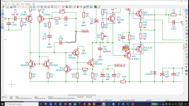
Could I ask you to post a schematic that shows which positions C1 and C2 are, that you are referring to?
Could I ask you to post a schematic that shows which positions C1 and C2 are, that you are referring to?
With the current values of C1, C2 & R for TMC I'm seeing a large increase in 2nd harmonics THD coupled with an equally large decrease in 3rd harmonics THD. The resulting THD levels vs frequency thus come out about the same.
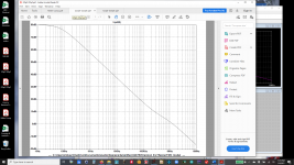
I attached a schematic clipping with the TMC C1, C2 & R labelled as such.
Hopefully once I optimize those values this increase in 2nd harmonic THD will be largely reduced.
I attached a schematic clipping with the TMC C1, C2 & R labelled as such.
Hopefully once I optimize those values this increase in 2nd harmonic THD will be largely reduced.
Attachments


Fired up the soldering station and worked though various values of C1 & C2 for TMC and found it's "happy spot" for my particular amplifier design/construction.
I measured performance at the following combinations using R = 1k for the following:
I am running THD sweeps today for all relevant parameters ( 3 power levels (1, 5, 45W), load (8, 4ohm), Miller vs TMC compensation, and sample rate (44.1/192 kHz) and will post a few graphs later that show anything interesting like the improvement switching in TMC over regular Miller compensation.
I may follow Baxandall's suggestion (the Baxandall papers) and vary the value of R down from 1K to optimize it while monitoring stability. I believe the consensus here is that Peter used 680ohms.
I measured performance at the following combinations using R = 1k for the following:
- C1 = C2 = 220pF (ratio 1X, eq. Miller cap of 110pF)
- C1 = 120pF, C2 = 470pF (ratio 4X, eq. Miller cap of 96pF)
- C1 = 120pF, C2 = 680pF (ratio 5.7X, eq. Miller cap of 102pF)
- C1 = 120pF, C2 = 1000pF (ratio of 10X, eq. Miller cap of 107pF)
I am running THD sweeps today for all relevant parameters ( 3 power levels (1, 5, 45W), load (8, 4ohm), Miller vs TMC compensation, and sample rate (44.1/192 kHz) and will post a few graphs later that show anything interesting like the improvement switching in TMC over regular Miller compensation.
I may follow Baxandall's suggestion (the Baxandall papers) and vary the value of R down from 1K to optimize it while monitoring stability. I believe the consensus here is that Peter used 680ohms.
Tried what? What are you referring to please
Local frequency-dependent oos ! As in LM3886
And not just the output stage. Model it and see for yourself. Miller doesn't get in the way here.As in the drawing? Is that putting the output stage totally inside the feedback loop?
- Home
- Amplifiers
- Solid State
- Feedback: Two pole vs. output inclusive ?