Hi everyone ! ")
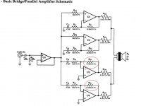
I read all the BPA200 datasheet, because I'm building it, and of course I know the manufacturer of the chip is right, BUT I DON'T understand why the feedback resistor (in red) is placed there !
The amp is used in inverse mode, so input signal enters in the inverse input, to have a inverse output to be connected to the -V of the speaker, and wow, you have the bridge!
The normal implementation (non inverted) use the feedback resistor to compensate the signal in, with the inverted signal, so, more feedback in the inverted input, less loud the sound will be...
So, WHY the inverted implementation don't use the feedback resistor connected to the non-inverted signal in? It don't make any sense to me...
Anybody ?!
Thanks !!
Attachments
Hi
The purpose of Rf & Ri in all four stages is to set the gain in accordance with the formula:
Vout/Vin = 1 + Rf/Ri
In this case, voltage gain is 22 or approximately 27 dB.
(Besides, if you connected the feedback to the non-inverting input you would have positive feedback, not negative. Oscillator anyone?)
Cheers
Rob
- Status
- This old topic is closed. If you want to reopen this topic, contact a moderator using the "Report Post" button.