Why the roll starts earlier.
Why this ideal opamp can not reproduce this very slow input signal to this not so heavy capacitive load (without this internal ringing)?
(Which it can drive directly so in tis case it's not about some output voltage/current limitations.)
Why this ideal opamp can not reproduce this very slow input signal to this not so heavy capacitive load (without this internal ringing)?
(Which it can drive directly so in tis case it's not about some output voltage/current limitations.)
Amplifier delay does not depend on Feedback. It depends on the amplifier bandwidth.
An amplifier with 100kHz bandwidth and feedback has the same delay as a second amplifier without feedback and with the same 100kHz bandwidth.
Amplifiers delay is rather meaningless anyway.
Any audio amplifier has > 20kHz bandwidth and
therefore the delay is < 50 us.
Important is the GROUP DELAY. This tells you if the amplifier has a good pulse response.
You add an extra pole, thus you push the amplifier towards oscillating, if you brake the loop and make a TiAN probe OLG plot you'll see how the phase margin is eroded
Why the roll starts earlier.
Why this ideal opamp can not reproduce this very slow input signal to this not so heavy capacitive load (without this internal ringing)?
(Which it can drive directly so in tis case it's not about some output voltage/current limitations.)
Well you put in the roll off yourself no, 100 ohms, 10nF?
Any audio amplifier has > 20kHz bandwidth and
therefore the delay is < 50 us.
No, these things have nothing to do with each other.
Jan
1) It's just surprising for me that an easy "controling task" like this is already too hard even for an ideal opamp.You add an extra pole, thus you push the amplifier towards oscillating, if you brake the loop and make a TiAN probe OLG plot you'll see how the phase margin is eroded
2) Sorry but if it's possible could you explain this for me in "transient mode" (so without poles and bode)?
So what holds back/slows down this opamp inside to produce a quicker response to this load without this ~30kHz oscillation?
Obviously its not the absolute output voltage/current limitation of the opamp.
I mean it potentially has all the outpout voltage and current that's needed to
charge this C perfectly even through this 100R and so it must be the controlling (sensing/acting) speed.
But what speed is it lacking exactly and what is the cause to this?
Again, if possible I'd be happy to undarstand it in transient mode for example with a single
transistor stage with internal voltages, current, capacitances, etc. Thanks in advance..! 🙂
1) It's just surprising for me that an easy "controling task" like this is already too hard even for an ideal opamp.
2) Sorry but if it's possible could you explain this for me in "transient mode" (so without poles and bode)?
So what holds back/slows down this opamp inside to produce a quicker response to this load without this ~30kHz oscillation?
Obviously its not the absolute output voltage/current limitation of the opamp.
I mean it potentially has all the outpout voltage and current that's needed to
charge this C perfectly even through this 100R and so it must be the controlling (sensing/acting) speed.
But what speed is it lacking exactly and what is the cause to this?
Again, if possible I'd be happy to undarstand it in transient mode for example with a single
transistor stage with internal voltages, current, capacitances, etc. Thanks in advance..! 🙂
But you put in a 100 ohms / 10nF filter. The opamp has nothing to do with it. Even with a perfect step opamp output, there is still phase shift AFTER the filter because that is where you pick off the output and feedback signal.
Doesn't matter whether the opamp is ideal or not, that filter is you phase shift source. And of course any phase shift internal to the opamp if present.
Jan
It does. I suggest page 23 of AD8045 datasheet, "driving capacitive loads", for a quick and straightforward explanation.
I guess it should untill the FB is taken after the RC.The opamp has nothing to do with it.
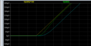
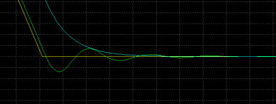
As it does in sim as well. Look at this 2nd layout with another opamp where the 100R-100n RC is put after the FB point.
The results:
- yellow: input signal (x100)
- green: 1st opamp output (FB corrected)
- light blue: simple RC output (RC outside from FB)
But why the ringing occurs thats what I would like to know.
Attachments
No, these things have nothing to do with each other.
Jan
Can you explain this to me? It seems natural to me, that a faster amplifier has a higher bandwidth?
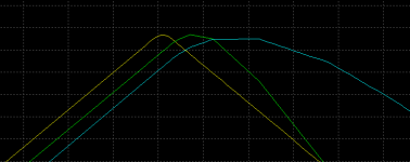
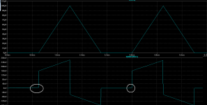
Other interesting parts of the signal. Good to see how this "delay" is varying...
- at the peak point
- somewhere in the middle of the negative slope
- at the end of the negative slop reaching 0
Attachments
Last edited:
@Cortez: You drive the opamp into current limitations with the 10 Ohm in 10nF. It is silly to assume that the opamp can correct any mistakes the designer made....
I don't think that is true. Black was well aware that amps are nonlinear in your sense that they create harmonic frequencies and that fb improves that. The requirement for fb is that the amp is a linear system meaning it is time-invariant.
A cursory look at datasheets would suggest that everything, from hFE to op amp small vs large signal response, is dependent on signal amplitude too, not only frequency. Thus if one wants to study Bode plots, he would need to draw a family of such plots, one for each amplitude. Which pretty much defeats the purpose of analyizing the circuit in the frequency domain.
@Cortez: You drive the opamp into current limitations with the 10 Ohm in 10nF. It is silly to assume that the opamp can correct any mistakes the designer made....
- It's 100R+100n right now
- The opamp can drive this C load (even) without this R effortlessly...!
- there isn't any output current limitations at this level
- just an internal "speed" problem and an unwanted ringing due to that...
Last edited:
Other interesting parts of the signal. Good to see how this "delay" is varying...
Edit: sorry: images corrected...
- at the peak point
- somewhere in the middle of the negative slope
- at the end of the negative slop reaching 0
Now we're talking. Armed with the third picture and a table like the one here:
http://www.ti.com/lit/an/slva381b/slva381b.pdf
you can evaluate phase margin. In closed loop and large signal.
Last edited:
With out the extra R you don't filter, you just load the amp hard at high frequencies, with the extra R you add a pole and thus filter within the loop, the extra delay is due the reduced slew rate, nothing to do with the delay trough the circuit.
With out the extra R you don't filter, you just load the amp hard at high frequencies, with the extra R you add a pole and thus filter within the loop, the extra delay is due the reduced slew rate, nothing to do with the delay trough the circuit.
Late edit, not entirely true, the cap wil form an R-C filter inside the loop, without the added R you filter over the output resistance of the OP amp.
The best way to see this and the added pole is to make a bode plot. Since you have LT-spice you can find the .asc file Loopgain 2 in the examples folder. It should be very simply to adjust for your circuit.
- It's 100R+100n right now
- The opamp can drive this C load (even) without this R effortlessly...!
- there isn't any output current limitations at this level
- just an internal "speed" problem and an unwanted ringing due to that...
No no no! The opamp can drive the R required current into C that ONLY means you have no slew rate limiting. But the filter action is still there and that causes phase shift. If the phase shift is too large, the NFB becomes PFB and the ´correction´ voltage being fed back actually starts to INCREASE the effective input voltage instead being subtracted. That means oscillation, your not quite there yet but the signs are there that it is close, ringing.
You can have oscillation if phase shift approaches 180 degrees. Here you have max 90 deg from the opamp internal roll off and 90 deg from the ´external filter´ Remove the external filter, and max phase shift is 90 deg and no possibility of oscillation.
Jan
- Status
- Not open for further replies.
- Home
- Amplifiers
- Solid State
- Feedback loop speed