Yesterday I started to read jan.didden thread ( another feedback question ) and some people keep arguing that feedback is slow and incapable of correct errors because of that delay, and this nuisance keep appearing in this forum and other sites again and again.
So I will try to show how fast feedback is, and what are the difference in speed of the different feedback compensation methods.
My last post was more than a year ago, so I may be a little rusty 🙂 .
So I will try to show how fast feedback is, and what are the difference in speed of the different feedback compensation methods.
My last post was more than a year ago, so I may be a little rusty 🙂 .

Sergio, you can look at the difference in the driving and the feedback signals at the LTP input transistors. Time difference is visible as a difference in the zero crossing, and the voltage divergence at the apex of the sine is the inverse of the excess Loopgain at the selected frequency.
Thanks Damir 🙂,
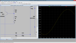
Hi Michael, I dont know if I full understand your last sentence, but I am measure the delay between input of the amplifier without the input filter and the output of the amplifier.
Hi Michael, I dont know if I full understand your last sentence, but I am measure the delay between input of the amplifier without the input filter and the output of the amplifier.
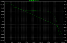
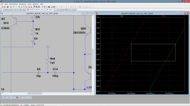
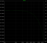
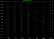
This is the open loop gain of the amplifier, the miller cap is the major cause of the delay, from the output of vas to the output of the triple darlington is only 12ns of delay.
if we change the miller cap from 33pf to 22pf the delay will decrease to 160ns, and the unity gain wil be at 1Mhz.
if we change the miller cap from 33pf to 22pf the delay will decrease to 160ns, and the unity gain wil be at 1Mhz.
Attachments
Last edited:
Some attention is needed when defining terms.
The delay 'of the feedback' is the delay inserted by components in the feedback path, and as these are typically just a few passive components (resistive divider) the delay is negligible (nanoseconds on a well designed PCB).
Propagation delay through the amplifier is a completely different thing, and could well be measured open loop too. So, some clarification is in order.
How do you measure the delay, if you look at the open loop plot there's a phase shift of app 90 degrees, does that mean that the delay changes with frequency..?
My mistake 😱, I can not measure the propagation delay like that.
So, for now I will measure the delay like you suggest in post #4 .
So, for now I will measure the delay like you suggest in post #4 .
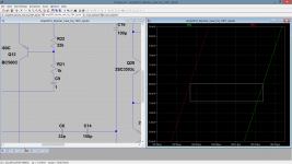

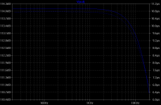
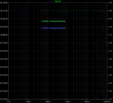
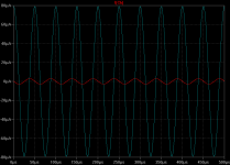
This is the phase diference between simple miller and the 2 pole compensation.
As one can see in the second image the phase at 20Khz is only 0.002º in the 2 pole compensation, and 1,5º in the miller. The phase is very linear at least to 100khz but there is some peaking at 600khz, this is not a sign of instability is inherent to this type of compensation.
As one can see in the second image the phase at 20Khz is only 0.002º in the 2 pole compensation, and 1,5º in the miller. The phase is very linear at least to 100khz but there is some peaking at 600khz, this is not a sign of instability is inherent to this type of compensation.
Attachments
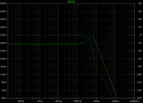
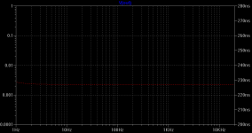
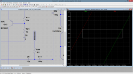
This is the delay of 2 pole compensation and is only 233ps ( pico second !!! )
this is a result that I us not expecting as even a 15cm wire has a propagation delay of 1ns.
Possibly there is a feedforward/phase lead effect around the comp stage?
Jan
Last edited:
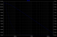
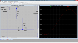
Jan, at first glance I think that the increase loop gain at audio frequency and the decrease in current in the miller capacity can be the reasons for that excellent result.
The 2 pole has 30db more gain at 20khz, and the current in the miller cap is only 3uA, in the simple miller is 80uA. This charging and discharging of the miller cap is for sure the main culprit of the delay in the amplifier.
The 2 pole has 30db more gain at 20khz, and the current in the miller cap is only 3uA, in the simple miller is 80uA. This charging and discharging of the miller cap is for sure the main culprit of the delay in the amplifier.
Attachments
Last edited:
Delay, is a much smaller influence than the limitation of gain. If all is considered minimal phase network and feedback helps correct the levels, then it will also correct the phase and thus also the delay..
Not sure if you can look at it that way.. But playing around with Spice indicate that something like that is going on. There's delay over components, but very little around the full circuit.
Not sure if you can look at it that way.. But playing around with Spice indicate that something like that is going on. There's delay over components, but very little around the full circuit.
- Status
- Not open for further replies.
- Home
- Amplifiers
- Solid State
- Feedback loop speed