Very nice, thanks for that! Similar to the Miller article I posted earlier.Pls post an example of such an audio amp that you have built with some measurement data. Looks interesting.
For all the fans of combining positive FB with NFB here is a useful article.
Refer to p56 in this link-
https://worldradiohistory.com/Archive-Radio-News/50s/Radio-News-1955-01-R.pdf
@marcel - the confusion was that current feedback by definition would be positive feedback, and voltage feedback would be negative feedback.
Thanks for the added subtleties.
@ruffrecords - I re-read your post and realize you didn't actually say that. I think I had a bad day ...
Jan
Last edited:
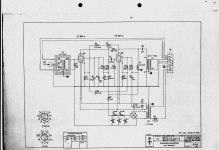
Attached is the schematic of the V72 amplifier from the 1940s used in recording studios throughout the world then and now including in the EMI mixers that recorded the Beatles and Pink Floyd. See how many types of negative and positive feedback you can identify.
Cheers
IAn
Cheers
IAn
Attachments
Neglecting anything that seems to be bias related, I see two overall feedback loops and one local loop in the second stage. There is overall voltage-to-voltage feedback via R12, R17 and R18 and voltage-to-current feedback via R12, R20 and R22. There is local current-to-voltage feedback via R19 in the second stage. The voltage-to-current feedback via R12, R20 and R22 is positive feedback, the other two loops have negative feedback.
Well done. Got them all.Neglecting anything that seems to be bias related, I see two overall feedback loops and one local loop in the second stage. There is overall voltage-to-voltage feedback via R12, R17 and R18 and voltage-to-current feedback via R12, R20 and R22. There is local current-to-voltage feedback via R19 in the second stage. The voltage-to-current feedback via R12, R20 and R22 is positive feedback, the other two loops have negative feedback.
Cheers
IAn
I have seen this used in other pro audio tube preamps. The V72 was replaced by EMI in the 60s by their own design because it was cheaper. It used an EF86 as the first stage followed by a single ended ECC88 with both triodes wired in parallel. Local shunt feedback was used around the ECC88. In the techincial description of the amp, EMI stated that this was to try to make the first and second stages produce similar distortion spectra but of opposite polarity and hence they would partially cancel.Do you happen to know the purpose of the local shunt feedback?
Cheers
Ian
In the techincial description of the amp, EMI stated that this was to try to make the first and second stages produce similar distortion spectra but of opposite polarity and hence they would partially cancel.
Cheers
Ian
Fascinating, I would never have guessed that.
In the technical description of the amp, EMI stated that this was to try to make the first and second stages produce similar distortion spectra but of opposite polarity and hence they would partially cancel.
Pete Millett's "Engineer's Amp" is also designed with a similar output scheme of distortion cancelling between stages. A higher than normal Primary Z OT and "Shunt Schade" N Fdbk around the output stage to lower distortion there, so the 1st stage can neutralize dist. with it. Apparently well liked, since it wiped out the supplies of 6JN6 outputs. Then the higher powered version wiped out the supply of 6HJ5s.
Last edited:
- Home
- Amplifiers
- Tubes / Valves
- Feedback and distortion in Single Ended amplifiers
