Hi everyone,
My name is Mark and I have been an audio enthusiast (not quite an audiophile) for over 30 years. Starting out on a very low budget and since then both acquiring and building better and more advanced audio equipment. Although my hearing between 11 kHz and 15 kHz faded over the past 20 years, my fancy for Single Ended amps never did. I just happen to be an engineer also.
Having built a 300B amp some 20 years ago, I now decided to create my own and (at least partly) original design. I didn't want to simply copy on of the 100 designs that can be found on-line, and that have been going around for 100 years. I now finished the design and documented it (see attached).
This design distinguishes itself in the fact that;
I will argue that feedback is a bad thing in a Single Ended amplifier, in case you place your output stage within the feedback loop, which is what (almost) every 300B amp schematic with feedback that I've seen is doing. I do believe it can be an interesting read for those that aren't more knowledgeable than me ;-) If you are, than please catch my errors.


*********
UPDATE
*********
The amplifier has now been built I have been listening to it (with and without NFB to compare) for a couple of days. The final schematic has been attached to this thread.
IT SOUNDS AMAZING. I have written my listening impressions in document 300B_R06 attached for those interested. It's the last few chapters. I'm guessing at this point that 300B tubes are MUCH harder to drive than people think, but if you take control (very low Z-out of the driver) of what happens at the grid of a 300B, the payoff is amazing.
Kind regards,
Mark
My name is Mark and I have been an audio enthusiast (not quite an audiophile) for over 30 years. Starting out on a very low budget and since then both acquiring and building better and more advanced audio equipment. Although my hearing between 11 kHz and 15 kHz faded over the past 20 years, my fancy for Single Ended amps never did. I just happen to be an engineer also.
Having built a 300B amp some 20 years ago, I now decided to create my own and (at least partly) original design. I didn't want to simply copy on of the 100 designs that can be found on-line, and that have been going around for 100 years. I now finished the design and documented it (see attached).
This design distinguishes itself in the fact that;
- Every aspect of the design is documented including background theory, calculations and rationale
- It uses my own 300B self-bias circuit design (using DN2540 that is now in supply again at Reichelt.com)
- It uses my own driver stage design using Negative Feedback (yes, feedback... and with good reason)
*********
UPDATE
*********
The amplifier has now been built I have been listening to it (with and without NFB to compare) for a couple of days. The final schematic has been attached to this thread.
IT SOUNDS AMAZING. I have written my listening impressions in document 300B_R06 attached for those interested. It's the last few chapters. I'm guessing at this point that 300B tubes are MUCH harder to drive than people think, but if you take control (very low Z-out of the driver) of what happens at the grid of a 300B, the payoff is amazing.
Kind regards,
Mark
Attachments
Last edited:
A couple of comments on first read though.
1. Gain is a ratio so the stage gain of the SRPP at 32dBV is incorrect. It is simple 32dB.
2. The SRPP is probably not the best choice for low distortion and with the output taken from the lower plate and the bottom triode cathode resistor unbiased you are not obtaining the best performance from it. For the load it is driving you do not really need an SRPP. You might be much better off replacing it with a 12AX7 mu follower which will give you both lower distortion and hgher gain.
Cheers
Ian
With the addition of a high value resistor from the output tube cathode back to the driver tube cathode, the OT distortion (magnetizing current and primary resistive loss) can be removed. It feeds back just enough drive signal to the driver to make up for the OT primary resistive loss from the monitored current, which includes magnetizing current. Patent # US4614914
https://patents.google.com/patent/US4614914A/en?oq=us4614914
MerlinB mentioned this last Spring.
Effectively inserts a negative resistance equal to the OT primary resistance. Should improve the output damping factor too. Probably can increase it some further to remove the plate Ra as well.
https://patents.google.com/patent/US4614914A/en?oq=us4614914
MerlinB mentioned this last Spring.
Effectively inserts a negative resistance equal to the OT primary resistance. Should improve the output damping factor too. Probably can increase it some further to remove the plate Ra as well.
Last edited:
Mark, very nice article, well written, well structured.
Will take some time to digest. As mentioned before dBV should be just dB throughout as it is just a ratio.
For now I would also mention that Menno van der Veen has worked on SE amplifiers leaving the output transformer outside the feedback loop.
He takes the feedback signal from the output tube anode. He calls it 'trans'.
You often mention the 'gate' of a tube, I assume that should be the 'grid'? ('Stuurrooster' 🙂 )
Jan
Last edited:
Yours is a well written and well researched academic exploration of current trends in the art. Please allow me to throw generalized caveats at that current state of art:
First, anytime anyone says anything, absolutely anything, that uses the word "feedback" in any way, is wrong. This is not hyperbole; this is Revealed Truth from original clay tablets.
Second, an output stage, valve plus transformer, isn't independent of its load. One without the other is a paper construct.
Third, gurus have their place, but honestly don't want folk to take their broader broadsides as gospel. Large, unstated and unexamined assumptions are a clue that someone's writing is at least partially poetic, or inspirational. This is different from deceptive, and different from "wrong".
All good fortune,
Chris
Hi Chris, I can't parse your 'First, anytime anyone says anything, absolutely anything, that uses the word "feedback" in any way, is wrong. This is not hyperbole; this is Revealed Truth from original clay tablets.' What do you mean by that? Surely not everything that can be said about feedback is by definition wrong? Although I would agree that a lot of it is!
I also agree that referring to the statements by guru's is not convincing - I would prefer facts and figures!
But I guess Mark would prefer to discuss his circuits ...
Jan
I also agree that referring to the statements by guru's is not convincing - I would prefer facts and figures!
But I guess Mark would prefer to discuss his circuits ...
Jan
Hi Ian,A couple of comments on first read though.
1. Gain is a ratio so the stage gain of the SRPP at 32dBV is incorrect. It is simple 32dB.
2. The SRPP is probably not the best choice for low distortion and with the output taken from the lower plate and the bottom triode cathode resistor unbiased you are not obtaining the best performance from it. For the load it is driving you do not really need an SRPP. You might be much better off replacing it with a 12AX7 mu follower which will give you both lower distortion and hgher gain.
Cheers
Ian
Thanks for commenting! You are correct regarding gain being in dB of course. In relation to the FFT views I used dBV so much that I also typed it where I shouldn't. I'll make corrections. Thanks for pointing that out.
The SRPP in itself shows a THD of 0.194% which indeed isn't that great. I'll experiment with a mu-follower to see if it provides any significant enhancement with the 12AX7 as part of the NFB loop. The added gain probably contributing most to lowering distortion further. If the impact isn't significant (currently at the level of 0.0096% THD due to the NFB) then I'll stick to the SRPP, simply because I'm building this into the limited available space of an existing amp (not because it's better). Again, many thanks for the suggestion and I'll explore it for sure.
Cheers,
Mark
Hi smoking-amp,With the addition of a high value resistor from the output tube cathode back to the driver tube cathode, the OT distortion (magnetizing current and primary resistive loss) can be removed. It feeds back just enough drive signal to the driver to make up for the OT primary resistive loss from the monitored current, which includes magnetizing current. Patent # US4614914
https://patents.google.com/patent/US4614914A/en?oq=us4614914
MerlinB mentioned this last Spring.
Effectively inserts a negative resistance equal to the OT primary resistance. Should improve the output damping factor too. Probably can increase it some further to remove the plate Ra as well.
Interesting patent! In this design I aim to explore the benefit of keeping the output stage OUTSIDE the feedback loop, as this seems to have a positive effect on the complex noise floor due to IMD. The patent seems to include the output stage in the loop. Although this may lower THD, that's not what I'm exploring. In fact... I don't want to touch the output stage as the assumption here is that the output stage of an SE amp provides a form of "desirable" distortion. We (some) seem to like it.
Kind regards,
Mark
Dear Jan,Mark, very nice article, well written, well structured.
Will take some time to digest. As mentioned before dBV should be just dB throughout as it is just a ratio.
For now I would also mention that Menno van der Veen has worked on SE amplifiers leaving the output transformer outside the feedback loop.
He takes the feedback signal from the output tube anode. He calls it 'trans'.
You often mention the 'gate' of a tube, I assume that should be the 'grid'? ('Stuurrooster' 🙂 )
Jan
Thanks for the post! Indeed I overused dBV and will make corrections.
I wasn't aware that Menno (I know him by name and know some of his designs) has explored a similar direction. I'll need to have a look, and just saw that he wrote a book on the 'trans' concept. It appears to be a little different in the sense that (to some extent) he is leaving the OPT outside the loop, yet connects to it's primary? I would guess that at least of a portion of what happens on the secondary OPT side will be reflected on the primary side. As such the OPT is not outside the loop completely, but I'm speculating a bit and need to really look into the principles. I'll need to buy the book 🙂
I'm more used to working with FETs than tubes, so indeed, I need to adopt the appropriate terminology and stop calling the grid a gate 🙂
Many thanks for bringing Menno's work to my attention!
Kind regards,
Mark
Mark said I would guess that at least of a portion of what happens on the secondary OPT side will be reflected on the primary side. As such the OPT is not outside the loop completely.
Good point. I think his main point is that you avoid the output transformer phase shift which makes it easier to apply a hefty feedback factor.
I send your paper to Menno and he tells me he is impressed 😎
Jan
Good point. I think his main point is that you avoid the output transformer phase shift which makes it easier to apply a hefty feedback factor.
I send your paper to Menno and he tells me he is impressed 😎
Jan
Hi Jan,Hi Chris, I can't parse your 'First, anytime anyone says anything, absolutely anything, that uses the word "feedback" in any way, is wrong. This is not hyperbole; this is Revealed Truth from original clay tablets.' What do you mean by that? Surely not everything that can be said about feedback is by definition wrong? Although I would agree that a lot of it is!
I also agree that referring to the statements by guru's is not convincing - I would prefer facts and figures!
But I guess Mark would prefer to discuss his circuits ...
Jan
I agree, just an opinion/statement doesn't cut it, and I would like to see argumentation and facts also. In fact, I will not even argue the statements made, because I simply don't know what the sonic effect will be. I need to hear it first, and would also love to hear the findings, as to how this sounds, from someone who actually listened to an amp with this type of design. Almost every SE amp that I've seen includes the output stage and transformer WITHIN the feedback loop. I tend to agree that this form of feedback in SE amps is not the way to go. It does however NOT represent what I'm talking to in any way. Let's be careful not to generalize the term feedback. I'm convinced that also Chris is actually listening to music at home that also passed through some kind of feedback and probably multiple feedback loops, somewhere in the audio chain (from source to speaker). And even if that assumption is false (which it most likely isn't), than the recording studio will have done so. A generalization to the point that "feedback is bad" simply doesn't make sense. This isn't the point of what I've written, as the document mainly homes in on the effect of low IMD at every amplifier stage and the effect of that on the "complex noise floor". I'll therefore stay out of any "feedback is back" discussion moving forward.
Besides the circuit, I am actually VERY interested in, and exploring, what we perceive as quality sound. Exploring the impact of complex noise in SE amps is what I'm now focused on, and in that sense the schematic and building it being a means to an end.
Thanks for your comments!
Mark
Wow!!! Thanks for doing that!Mark said I would guess that at least of a portion of what happens on the secondary OPT side will be reflected on the primary side. As such the OPT is not outside the loop completely.
Good point. I think his main point is that you avoid the output transformer phase shift which makes it easier to apply a hefty feedback factor.
I send your paper to Menno and he tells me he is impressed 😎
Jan
Coming from someone like Menno who basically "wrote the book", that's a HUGE compliment. Now I'll have to buy the book too 🙂
I'm happy this resonates (at least with some), given that this is my first stab at something like this. I have however used many only sources to build on an bringing things together within the context of an SE amplifier, or at least, that was the intent.
Thanks again Jan!
Cheers,
Mark
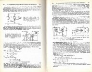
Hi jhstewart9,Positive FB reduces internal impedance of the output stage. Scanned from RDH4
The image on IMD attached in error couldn't be removed.
Are you referring to illustration 7.51B?
Thanks,
Mark
Thanks for commenting everybody. I have incorporated following feedback in this version;
Further comments and feedback remains welcome!
Kind regards,
Mark
- Talk about "grid" instead of gate in relation to tubes
- Use dBV for indicating a signal level, not for gain or other ratios
- Added a comment regarding the use of mu-follower for the 12AX7 (pending further evaluation)
Further comments and feedback remains welcome!
Kind regards,
Mark
Attachments
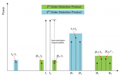
I think you may be very right about some things, but I also think the HD is a bit of a red herring...
I've been hunting down research papers (like the one attached, and a couple of others if I can find them) to get to the bottom of things.
As can be seen, controlling the current tends to provide more linear results when measuring and validating the end result with a microphone.
Due to the traditionally high output resistance of tube amps, it seems the designers have been doing it right all along, but the higher distortion was harder to explain away, so "nice sounding distortion" became a myth that just won't die.
The same mechanisms that create HD unavoidably also create IMD when they have the opportunity, so to me the idea of the sound being somehow 'sweetened' with special effects makes no sense at all.
What's really missing in the equation is a 3rd factor: the speaker load.
I think it's a really bad habit for some people to attempt to treat an audio system as a collection of "independent components". They are not independent. Unless careful steps are taken to deliberately avoid it, the speaker almost invariably changes the amplifier's purported internal THD rating. Even a vastly over-simplified LCR circuit for the speaker can blow up an amplifier's THD by a factor of 10 or more in simulations. And that's with no speaker distortion, only a phase shift that sabotages the otherwise ideal performance of the negative feedback. And that's where I think you've got it spot on by avoiding unbuffered negative feedback on the output stage. In real life it's even worse, because it's not just benign phase shifts, but also non-linear inductance appearing in series, mechanical reverb, and chaotic glitches from the permanent magnet.
On a related note....
Step response graphs ring alarm bells for me: a steady voltage is applied, and what happens then? The cone traverses a bizarre scenic route, usually oscillating back and forth many times before settling. What seems to happen is the bass is fairly close to 'critically' damped, while at a much higher frequency, the voice coil -- in spite of a high damping factor -- is mysteriously unable to absorb the reverberating energy from the cone. All it takes is that the reverberations shift the mechanical phase 180 degrees, and negative feedback becomes positive feedback, and actually reduces stability, making cone break-ups decay longer than they need to.
Attachments
Mark said I would guess that at least of a portion of what happens on the secondary OPT side will be reflected on the primary side. As such the OPT is not outside the loop completely.
Good point. I think his main point is that you avoid the output transformer phase shift which makes it easier to apply a hefty feedback factor.
I send your paper to Menno and he tells me he is impressed 😎
Jan
That was also L. V. Viddeleer's argument for using feedback from the transformer primary in the 1950's, see pages 449 ... 457 of the October 1954 issue of Radio Electronica,
http://nvhrbiblio.nl/biblio/tijdschrift/Radio%20Electronica/1954/Radio%20Electronica%201954-10-OCR.pdf
Viddeleer discussed his tone control more thoroughly in the August 1953 issue, pages 29 ... 32 and 64, see http://nvhrbiblio.nl/biblio/tijdschrift/Radio Electronica/1953/Radio Electronica 1953-08-OCR.pdf and in the September 1953 issue, pages 19 ... 22 and 38, see http://nvhrbiblio.nl/biblio/tijdschrift/Radio Electronica/1953/Radio Electronica 1953-09-OCR.pdf
Nice to see confirmation on reducing the tube Ra (extension) to the Neg. Impedance OT compensation idea. Eliminating the real "Gorilla monster" (speaker effects) can be further accomplished by lowering the output Z by Neg. Fdbk at the OT primary as well (avoiding OT phase problems). Only a specific amount of Pos. Fdbk is allowed to fix the Ra and OT primary resistance, plus magnetizing current, so the combo gives great flexibility and accuracy if done right.Positive [current] FB reduces internal impedance of the output stage.
Hi jhstewart9,
Are you referring to illustration 7.51B?
Thanks,
Mark
Are you referring to illustration 7.51B?
-----------------------------------
Yes, 7.51B can be used to lower & even eliminate plate & external resistances.
Cathode to Cathode Positive FB,
I used the circuit of Fig 7.51A to get enough gain in a guitar amp I built for a friend.
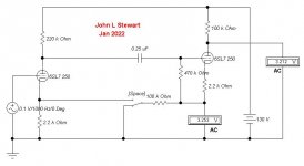
It was PP 25L6s, pulls from some IBM data processing of the era, around 1955. The OPT was a Hammond 125D, so about 6 Watts. The driver used is a very ordinary 6SL7 triode followed by a phase splitter triode in the same bottle. So with the connexion shewn there was about 10 db of positive FB. And full loop NFB as well.
The PS was a 340V CT transformer with a 25V , 150 mA heater winding. With a 50Y6GT rectifier there was 180V B+ to work with. The front end had a 6BH6 on the Mic input while the guitar pickup ran thru half the 12AX7. The other half of the 12AX7 provided basic losser type tone controls.
I never tried the other circuit but did build a PP 6AQ5 amp with positive current FB from a sampling resistance in series with the loudspeaker. That amp also had full loop NFB & was built circa 1958, need to look in my notes.
When tested on a speaker load without the +ve FB, the voltage across the speaker VC rose as we would expect. But with some +ve FB, the resonant hump became smaller & disappeared. More +ve FB & the speaker hump became a valley. Finally the amp would break into oscillation. For the curious & others the recipient was a former Luftwaffe pilot I met while working at DeHavilland Aircraft.
-----------------------------------
Yes, 7.51B can be used to lower & even eliminate plate & external resistances.
Cathode to Cathode Positive FB,
I used the circuit of Fig 7.51A to get enough gain in a guitar amp I built for a friend.
It was PP 25L6s, pulls from some IBM data processing of the era, around 1955. The OPT was a Hammond 125D, so about 6 Watts. The driver used is a very ordinary 6SL7 triode followed by a phase splitter triode in the same bottle. So with the connexion shewn there was about 10 db of positive FB. And full loop NFB as well.
The PS was a 340V CT transformer with a 25V , 150 mA heater winding. With a 50Y6GT rectifier there was 180V B+ to work with. The front end had a 6BH6 on the Mic input while the guitar pickup ran thru half the 12AX7. The other half of the 12AX7 provided basic losser type tone controls.
I never tried the other circuit but did build a PP 6AQ5 amp with positive current FB from a sampling resistance in series with the loudspeaker. That amp also had full loop NFB & was built circa 1958, need to look in my notes.
When tested on a speaker load without the +ve FB, the voltage across the speaker VC rose as we would expect. But with some +ve FB, the resonant hump became smaller & disappeared. More +ve FB & the speaker hump became a valley. Finally the amp would break into oscillation. For the curious & others the recipient was a former Luftwaffe pilot I met while working at DeHavilland Aircraft.
Attachments

- Home
- Amplifiers
- Tubes / Valves
- Feedback and distortion in Single Ended amplifiers