
MikeS - how about contributing?
nonlinear systems are more diverse and therefore have few generalizations to compare with linear system theory - but the Lurie' system with saturation nonlinearity is well studied and the basis for discussing jump resonance and related phenomena
the 100dB math isn't that difficult - and I did say 20MHz would be optimistic and require mosfets
10 KHz to 3 MHz is 2.5 decades of frequency, 40 dB/decade gives the 100 dB and leaves enough room for modest phase margin with mosfet outputs which could allow loop gain intercept > 10MHz
Bode's maximum gain characteristic shows peaking in the gain response can stretch out another octave, covering 20 KHz "audio" frequency range - I could even argue that flat loop gain to 20KHz is not strictly a requirement with music generally being held to have ~ 3KHz power bandwidthbandwidth - or that audio frequency is best measured logarithmically and 20 - 20K is 10 octaves, therefore even maintaining high loop gain to 5 KHz represents covering “80%” of the audio bandwidth
I value the chance for a higher level discussion but feel the contribution is all running one way here
couldn't say why you’re being moderated but continue "sharpshooting" without attempting substantive posts of your own and I will put you on "Ignore"
I have designed a simple amplifier with only 1 chip and one nested discrete output loop which achieves THD < 0.00005%, possibly lower than Halcro,
This is my feeling Greg, that it is time to get down to business, moreover this was decade ago and wouldn't affect your IP/current wellfare.
Attachments

dimitri said:
This is my feeling Greg, that it is time to get down to business, moreover this was decade ago and wouldn't affect your IP/current wellfare.
Oh, Dimitri, you must be feeling very uncomfortable also lot of curiousity prevails on your mind regarding Greg's claim...
")
mikeks said:
In which case the frequency of unity loop-transmission would exceed 20MHZ!

Correction....that should read:
In which case the frequency of unity minor loop-transmission would exceed 20MHZ!

Re: MikeS - how about contributing?
Hi JCX..
Actually i think you'll find i was responding to 1001's post...
jcx said:....I did say 20MHz would be optimisitc and require mosfets....
Hi JCX..
Actually i think you'll find i was responding to 1001's post...
Re: MikeS - how about contributing?
Indeed....what i am struggling with is the relevance of all this in respect of double-pole compensation in general....
jcx said:...nonlinear systems are more diverse and therefore have few generalizations to compare with linear system theory - but the Lurie' system with saturation nonlinearity is well studied and the basis for discussing jump resonance and related phenomena
Indeed....what i am struggling with is the relevance of all this in respect of double-pole compensation in general....
mikeks said:
Exceedingly unlikely...unless said compensation includes the output stage....
Even then the 100dB of loop gain you've alluded to 1001 will only cover the second and output stages.
Major loop gain will remain unchanged, as the input stage is still left out in the cold at HF.
Re: MikeS - how about contributing?
OK..
jcx said:.........I will put you on "Ignore"
OK..
apologies for seeming over sensitive but it happens that 1001 is simply echoing my post #6 in this matter - so your criticism appears to take my statement out of its qualifying context and then repeats my other points too - increasing my annoyance
I am stretching to try make some general statements about the limits of negative feedback and commentary from someone who has explored audio power output stages in more detail would improve the estimates of what may be practical
I am stretching to try make some general statements about the limits of negative feedback and commentary from someone who has explored audio power output stages in more detail would improve the estimates of what may be practical
jcx said:apologies for seeming over sensitive
I think if you want to have an intelligent discussion, you will have to accept that fact that people don't agree with you all the time. Rather than blaming their not accepting their theories, you ought to focus on making your points acrossed, which from my vintage point of you you aren't doing.
Instead, you seem to be frustrated at your inability to convince people of your view points - which I don't know how valid they are.
Just my observations.
MikeS's one liners are not "intelligent discussion" – I suspect he does have valid technical arguments to back them up but he isn’t making them here
There is lots of feedback theory that I'm still struggling with and meaty discussions would be helpful but that requires comparably detailed presentations of alternative viewpoints - there are people I expect I could learn from here but given the time I spend on trying to compose intelligent posts I can understand the relative lack of higher level theoretical discussion
Your earlier objection to my quickie on the limits of feedback frequency/phase shift could be explored further – if I were refining my presentation I would say that the main practical limit to feedback is the uncertainty in the high frequency transfer function – an output stage with a known, fixed minimum phase gain characteristic could be equalized up to the next faster stage’s uncertainty limit – but carrier transit time and packaging parasitic L,C add nonminimum phase or additional unaccounted phase shift which give lower practical limits to feedback
I would have to reread some material to get Bode’s T, F and precise definitions correct but with the assumption that all real physical systems having 2 more poles than zeros Bode’s phase integral relation is commonly presented as saying
frequency weighted area of ln(|“negative-feedback”|) = ln(|“positive feedback”|)
so that at high enough frequencies all “negative feedback” amplifiers exhibit positive feedback and increased sensitivity to amplifier “gain” variations ( but this happens where the loop gain is less than unity or you will have oscillation )
when you have to budget for nonminimum phase shifts in your system it comes out of the negative feedback area reducing the maximum negative feedback you can use by limiting the highest frequency at which feedback can reamain "negative"
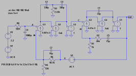
Just for grins, I thought I'd post an example of a concept I'm working on. I don't know if I'll be able to work out the bugs in simulation or not, but it's an interesting exercise anyway.
The idea was to combine the nested feedback concept that Greg has been talking about with a three-pole compensation approach. The attached graphic shows the concept. I'll attach the actual LTSpice file in a following post.
The transconductances G1 and G3 model the actual value of the transconductance of an input diff amp, so that the compensation components from the conceptual amplifier could be used in an actual amplifier with the values unchanged. The transconductances G2 and G4 represent an ideal VAS (okay, TIS), such that the transfer function of the VAS is completely controlled by the compensation component values. The idea was to have a unity loop gain frequency for the overall loop of 1 MHz, with two zeros, both at 100 kHz, and three poles at the origin (approximately). The rolloff of overall loop gain would be 20 dB/decade at the unity loop gain frequency. Thus at 100 kHz, the loop gain would be around 20 dB, increasing as frequency goes down at a rate of 60 dB/decade. This allows for a global feedback factor of around 60 dB at 20 kHz.
Starting from the output, the inner loop from point "C" to "out" is a normal power amplifier, except it's configured as an integrator, but with a zero at 100 kHz. This accounts for one of the two zeros at 100 kHz that I previously mentioned. The inner power amp's minimum gain (except at very high frequencies) is 21 (when C5 is a short). Thus the circuitry to the left of node "C" need only be line level, since it will take just a few volts (at most) at node "C" to drive the power amp to full power. The gain-bandwidth product of the inner power amp is 21 MHz, so with its gain of 21, its unity loop gain frequency will be 1 MHz. This would normally degrade the phase margin of the overall loop by 45 degrees, except for the fact that the transfer function of the global feedback network (R5, R6 and C7) has a zero at 1 MHz, followed by a pole at 21 MHz. Notice that at the unity loop gain frequency of 1 MHz, the gain from node "C" to the output, then back through the feedback network to node "B" is almost exactly one. So the outer amplifier (G1, G2, E3, etc.) should be designed such that if it had a feedback factor of one, that its unity loop gain frequency would also be 1 MHz. This is determined by the gm of G1 and the product of C2 and C3 divided by their sum. R7 establishes the frequency of the zero, which is also 100 kHz.
By expressing the open-loop gain A as a ratio of polynomials N(s)/D(s), it's easy to see that the zeros of A will also be present in the closed-loop gain. This causes a potential problem with a slight frequency response peaking and overshoot in the closed-loop square wave response. This is prevented by the input LPF, which has a pole at 100 kHz to cancel out the closed-loop zero. This also prevents slewing with square wave inputs and sets the bandwidth of the closed-loop amplifier (which would otherwise be 1 MHz).
Attachments
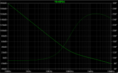
Attached below is a plot of the loop gain vs. frequency. It can be seen that the unity loop gain frequency is indeed 1 MHz as designed, and the (idealized of course) phase margin is about 80 degrees. Subtract 360 degrees from all phase values. Feedback at 20 kHz is a little more than 60 dB. But the inner amplifier also has feedback around it. Its open-loop gain looks like an integrator, while its feedback factor looks like a differentiator at audio frequencies. Thus its loop gain is nearly constant over the audio band, and comes out to about 20 dB.
Attachments
- Status
- This old topic is closed. If you want to reopen this topic, contact a moderator using the "Report Post" button.
- Home
- Amplifiers
- Solid State
- Feedback & audio amp