Well, I didn't get to my new amp project yet, nor any of the guitar amps, but I did finally find the time to restore my Radio Craftsmen RC-2 audio amp, which has a push-pull 6V6 circuit.
I originally got this on Ebay for around $115. Looks like someone tried to use the same tubes, but completely rewire it in the late 60's.
Most of the wiring was changed under the chassis. The tubes are original, the power tranny, but they put in a new(universal) output transformer from Triad back in those days, now obsolete, an S-57Z.
I will have to isolate it and do some tests to see if they wired that rignt with the 6 secondary taps, but I can't find any info directly on the web.
I can do ratio tests with my variac and scope it out directly that way.
For one thing, it didn't work originally because they never wired the 6.3v to the 6J5 input (metal tube) correctly.
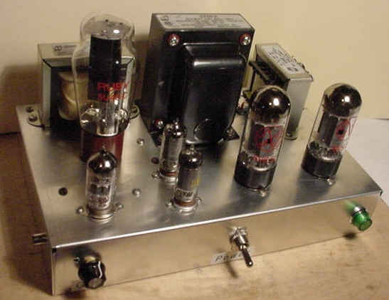
Anyway, I gutted the entire underside, bypassed the can caps, and got it working in one good day of work, no hum and nice-sounding. About 13 watts. No switch, volume, fuse or tone controls, just plug it in. I always put my glasses on and stand back 6 feet the first time I test something like this, after a quadruple check on my work.
They say the unit was from 1952, but I ordered a Sams Photofact on the web for $5 and the date on that was 1948. It does work fine now, with all the original 1948 component values.
It does run the feedback from the 16 ohm terminal, though the schematic calls for the 6 ohm terminal, what's the best value for this? As I said, the dufus that messed it up may have wired the output trafo wrong too (which is the only thing not original on this and I didn't change that yet)
and it seems to play more tonally better and slightly louder when I hook my 8 ohm speaker to the 16 ohm terminals.
The plates on the finals do glow red a bit, but even when I connect my speaker to the 8 ohm terminals.
The 6V6GT's seem to be getting about 370v on the plates.
I'm going to be building that college site 6V6 amp in the next week or so (which I posted way early on this thread), which is similar. With all the discussion on the guitar amps, (which is next on my list), I hope to come across a good "tone control", or in particular a "bass boost", that I can also apply to a hi-fi amp like this. All my tube amps have good fidelity at midrange, cymbals, horns, trumpets, etc., but really lack on the same albums for bass, compared to when my wife plays the albums in her ghetto blaster. I'll look into this, maybe with some help. I've got to go out of town for 3 days, before I get a chance to heat up my soldering iron again 🙁
Anyway, wanted to paste a few shots, the top and bottom, at the stage the RC-2 is at now, definitely a success, may need tweaks to the output trafo:


I originally got this on Ebay for around $115. Looks like someone tried to use the same tubes, but completely rewire it in the late 60's.
Most of the wiring was changed under the chassis. The tubes are original, the power tranny, but they put in a new(universal) output transformer from Triad back in those days, now obsolete, an S-57Z.
I will have to isolate it and do some tests to see if they wired that rignt with the 6 secondary taps, but I can't find any info directly on the web.
I can do ratio tests with my variac and scope it out directly that way.
For one thing, it didn't work originally because they never wired the 6.3v to the 6J5 input (metal tube) correctly.
Anyway, I gutted the entire underside, bypassed the can caps, and got it working in one good day of work, no hum and nice-sounding. About 13 watts. No switch, volume, fuse or tone controls, just plug it in. I always put my glasses on and stand back 6 feet the first time I test something like this, after a quadruple check on my work.
They say the unit was from 1952, but I ordered a Sams Photofact on the web for $5 and the date on that was 1948. It does work fine now, with all the original 1948 component values.
It does run the feedback from the 16 ohm terminal, though the schematic calls for the 6 ohm terminal, what's the best value for this? As I said, the dufus that messed it up may have wired the output trafo wrong too (which is the only thing not original on this and I didn't change that yet)
and it seems to play more tonally better and slightly louder when I hook my 8 ohm speaker to the 16 ohm terminals.
The plates on the finals do glow red a bit, but even when I connect my speaker to the 8 ohm terminals.
The 6V6GT's seem to be getting about 370v on the plates.
I'm going to be building that college site 6V6 amp in the next week or so (which I posted way early on this thread), which is similar. With all the discussion on the guitar amps, (which is next on my list), I hope to come across a good "tone control", or in particular a "bass boost", that I can also apply to a hi-fi amp like this. All my tube amps have good fidelity at midrange, cymbals, horns, trumpets, etc., but really lack on the same albums for bass, compared to when my wife plays the albums in her ghetto blaster. I'll look into this, maybe with some help. I've got to go out of town for 3 days, before I get a chance to heat up my soldering iron again 🙁
Anyway, wanted to paste a few shots, the top and bottom, at the stage the RC-2 is at now, definitely a success, may need tweaks to the output trafo:
The plates really shouldn't glow. You ought to increase the bias to stop that happening.
It doesn't matter which tap the feedback comes from, only the AMOUNT of feedback. If you switch it to the 8 ohm tap feedback will be reduced, which may or may not be what you're after.
Here are some useful articles, including a "bass boost control"
http://www.thermionic.info/
It doesn't matter which tap the feedback comes from, only the AMOUNT of feedback. If you switch it to the 8 ohm tap feedback will be reduced, which may or may not be what you're after.
Here are some useful articles, including a "bass boost control"
http://www.thermionic.info/
I'm finally getting ready to start on the "new" 6V6 amp, still working on a few details, but getting ready to start drilling tomorrow, hopefully.
I've come up with this layout, the sockets & trafos are just sitting on top for now, this seems to be the most aesthetic.
The choke is to the left, and the OPT (at 90 degrees) at far right.
Just in front of the choke is the socket for the 5U4GB, and the octal sockets to the right are for the 6V6's.
Just to the left will be two 6AU6 phase inverters, and at the very bottom left is the first two stage tube, a 12AU7.
My only concern is that the 12AU7 may be a bit close to the rectifier tube, is that a concern, or is 2 1/2" from center to center of the sockets enough? I guess also that I should face the plate side of the 5U4 tube socket away from the 12AU7, as that's where the AC is connected,
also making sure the filter caps, etc., are way in the back.
I like the linear design of the stages from left to right (this is a PP monoblock) and the iron in back. One thing I also could do is drop the choke and just use a resisitor in the PS as the Radio Craftsmen I restored (above) didn't have a choke, and it sounds just fine.
Well, I did get my new prototype done and it works like a champ, about 14 watts of nice hi-fi. After I tested the voltages out and triple-checked the wiring (and used old dubious expendible tubes first), I put in my new JJ & Ruby tubes, for the 6V6's, 12AU7 and 5U4, the only ones that are NOS are the 6AU6's, one of these is a new old Magnavox, the other a GE.
Ran it for 4 hours from an old late-80's CD deck, and it did well.
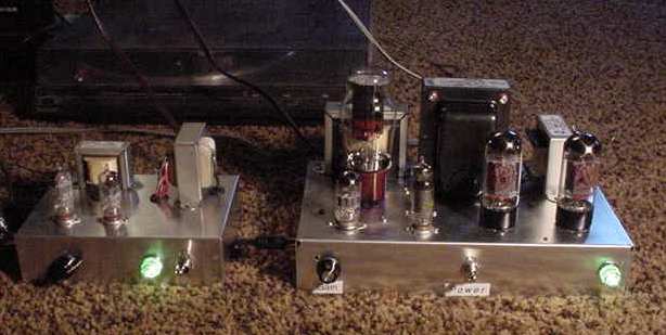
And running it on the living room rug feeding a turntable into the preamp first to get more gain:
Ran it for 4 hours from an old late-80's CD deck, and it did well.
And running it on the living room rug feeding a turntable into the preamp first to get more gain:
First post in thread Schematic is from the MusicMaster Bass CFA7010
Cab, amp with speaker = 22 Lb
12 watt 10" speaker
I happen to have bought one this very day,
see photos at
http://www.tgdns.com/FenderAmp/MusicMaster.htm
This unit originally used 6AQ5 rather than the 6V6GT
Fender was owned by CBS in 1970 when Musicmaster Bass was introduced
Leo Fender left RCA/Fender in 1971, starting a new company
Fender Amp Time Line http://www.ampwares.com/ffg/time_line.html
From what I can tell by researching my MM Bass amp 1210 it looks like RCA/Fender started using the 6V6 in late 1971 early 1972.
My cursory examination of the Schematic reveals the same circuit
While I have not yet compared resistor and cap values I can at this time verify that all Xformer part numbers are the same for the units made with 6AQ5 or 6V6GT
This might explain why some of the specs on the 6V6 schematic seem a bit off.
Yes, those 6V6-based amps sure have a great sound and shouldn't be overlooked, for either guitar or hi-fi. Very sweet sounding if done up right, and enough power for living-room type scenarios.
They don't require expensive trafos due to the lower power, and are great projects for either restoration or the from-scratch DIY-er.
Best of luck with yours, and have fun...
They don't require expensive trafos due to the lower power, and are great projects for either restoration or the from-scratch DIY-er.
Best of luck with yours, and have fun...
frank754 said:Yes, those 6V6-based amps sure have a great sound and shouldn't be overlooked, for either guitar or hi-fi.
A favorite quote in this regard is, "It's REALLY hard to make a bad sounding 6V6 amp." 😉
Though some commercial designers have gone that extra mile to do so, I've yet to hear a bad DIY one 😀
Cheers!
BTW said:Pointdexter's Music Machine is a very nice 6V6 PP amp...
http://www.audiotropic.net/Projects/machine1.html
Yes it is. I've heard it several times on his speakers and mine. It loves my speakers. Great amp!
(Don't know how it would be for guitar, tho.)
Well, as to cost and availability:
Fender Musicmaster Bass Style Interstage Driver, 026847
$ 38.03
By comparision, implementing a LTP PI:
Tung-Sol 12AX7 - $14.95
Belton 9 Pin Miniature Chassis Mount Socket: 3.25
6 resistors: $2.00
3 capacitors: 3.00
$23.30
So it seems to me that cost really shouldn't be a major issue.
How do amps with such an interstage transformer SOUND compared to a tube PI? My understanding is that the phase invertor contributes significantly to the overall tone.
Joe
Frank,
It's a fact of life that the transformers ("iron") are a major part of the cost of any tube power amp project. Even IF it's available, that phase splitter trafo is going to put some sort of dent in your bank balance.
Those of us involved in the "El Cheapo" project went to GREAT lengths to control "iron" costs. Advantage was taken of an inexpensive replacement O/P trafo for Fender Deluxe guitar amps in the HIFI amp. "What goes around, comes around." You use can most of the "El Cheapo" circuitry to advantage in your MI project. Not having to worry about deep bass, allows the use of the available ultralinear taps. The 'AQ5 "El Cheapo" uses is electrically "equivalent" to the 6V6. So, component value changes are not necessary. Whether or not you retain the loop NFB is up to you.
Since a MI amp has only 1 channel, you could use a Triad N-68X in the voltage doubler. Other savings are possible too. 470 muF. 'lytics in the doubler stack are but 1 example.
edit: fixed typo
- Status
- Not open for further replies.
- Home
- Amplifiers
- Tubes / Valves
- Favorite easy 6V6 push-pull circuit?