darkfenriz said:seriously current conveyor is a similar concept to operational amplifier, but it has two low impedance inputs and a high impedance output, nomen omen.
It has a intrisic speed, because there is no voltage gain inside.
Your patterns may work, but every transimpedance stage made around a resistor in negative feedback loop may have problems with stability.
It's because from 'voltage' point of view, input impedance is infinite, and resistance in feedbackloop is given, so the 'voltage' gain is below 1, which is something most opamps hate.
That's why I am going to use video opamps.
Are current conveyors available as ICs?

Actually i am not concious of any current convoyour IC.
edit: maybe you may use a current feedback amplifier with non-inverting input grouded
As for opamp stability, no opamp likes voltage gain below one, especially fast video opamps. A capacitor in feedback loop is often mandatory. I suggest you studdied circuits designed for fast photodiode amplifiers, they serve the same purpose which is converting current to voltage and there is much research there, for example on how to tailor feedback capacitor for macimum gain*bandwidth.
Lumba Ogir said:Wavebourn,
just like in audio, overall negative feedback is really a nuisance here.
Which overall negative feedback?

The first one is a current to voltage converter, with close to zero input resistance to prevent cross-talk between signals I measure.
The second one, is a maximum-possible-gain amp with logarythmic overdrive function; the 3'd one has a positive feedback, a flip-flop with well defined hysteresis to shape output and prevent oscillations.
Do you know what are you talking about, Lumba?
'Which overall negative feedback?'
That in the 1st opamp e.g., the I/V converter. The FB ratio is defined by Zol/R1 😉
That in the 1st opamp e.g., the I/V converter. The FB ratio is defined by Zol/R1 😉
PMA said:'Which overall negative feedback?'
That in the 1st opamp e.g., the I/V converter. The FB ratio is defined by Zol/R1 😉
Oh eah, Lumba spotted it right away! No good for audio!

darkfenriz said:maybe you may use a current feedback amplifier with non-inverting input grouded
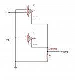
Like is drawn on my pictures?
Thanks! 🙂
What you specified you want in the first post and what you are drawing don't seem to relate.
What exactly is the function required?
What exactly is the function required?
I need to compare 2 currents when they flow in different directions, if to say strictly. Both may swing between -20 mA to +20 mA, up to 1 MHz frequency.
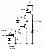
darkfenriz said:Peter Current Conveyour
Adam,
thanks, that one just made me spill coffee on my keyboard.
Best laugh i had in ages at this club.
darkfenriz said:Actually i am not concious of any current convoyour IC.
edit: maybe you may use a current feedback amplifier with non-inverting input grouded
As for opamp stability, no opamp likes voltage gain below one, especially fast video opamps. A capacitor in feedback loop is often mandatory. I suggest you studdied circuits designed for fast photodiode amplifiers, they serve the same purpose which is converting current to voltage and there is much research there, for example on how to tailor feedback capacitor for macimum gain*bandwidth.
Current conveyor has no voltage gain, *may* have current gain. What you would need is something like a MAX435 or 436, which unfortunately is obsolete, but you can build one from 2*AD844 or 2*OPA866. Edit: should be OPA860
Obviously for comparing current you want current mode circuits for high speed, not influenced by parasitic capacitances on nodes that have voltage swing.
jd
Wavebourn said:This one looks better, for 20 mA input currents:
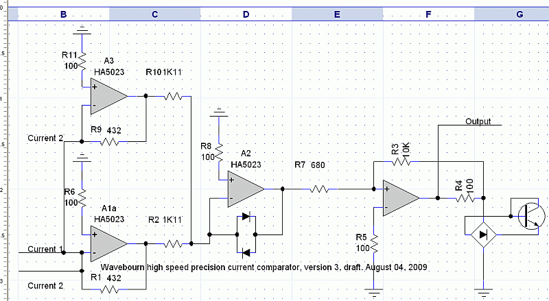
A minor point: I think there is a (trivial) miswiring". There should not any link between A1a and A3 inverting inputs.
A major point: I would have to experiment with *real* circuit - not spice - but my concern is about precision, noise and speed.
The HA5023 bandwidth is high and comparatively high is the noise. Which is the amplitude of the noise *seen* by A2 input when Current 1 = Current 2?
I think it would be necessary some DC hysteresis around A2 to prevent oscillation and some AC hysteresis as well to improve speed. See Pease's paper.
These improvement would be beneficial also with slow varying currents (Is your signal a 1MHz sine wave or ranges DC up to 1MHz?)
About precision you didn't state any figures: do you need 8 bit or 24 bit precision?
HA5023 is a current feedback amplifier and his inverting input has a bias current *not* comparable with a subpicoampere fet input amplifier. 20 mA is a relatively high current but be aware with bias currents and drifts
Wavebourn said:I need to compare 2 currents when they flow in different directions, if to say strictly. Both may swing between -20 mA to +20 mA, up to 1 MHz frequency.
Ok, the summing amp is the right way to do it. The single amp is fine. But I would use a comparator for the comparator function as they are better suited for that role than op-amps.
Why are you putting a bridge rectifier on the output?
Thank you for ideas gentlemen!
I will breadboard and report as soon as finish my current project.
Cheers!
I will breadboard and report as soon as finish my current project.
Cheers!

Thank you Jan, but I need as less of errors right in the point of comparison, as possible, that's why I decided to use an inverting connection and feed both signals to the same point. Such a way both signals meet the same capacitance, the same non-linearities, the same delay.
- Status
- Not open for further replies.
- Home
- Amplifiers
- Solid State
- Fast and precision current comparator