Yes, that is what I am thinking now too (it takes me longer to come to some conclusions).Good channel could show 14K rather than 33K because of shunt resistance paths. But there has to be a reason for widely different in-circuit resistance seen across R12 between channels.
As for C3 leakage, I'll check the voltage across R15.
Finally fixed it today. It wasn’t the voltage sensing resistor after all. I will write up tomorrow.
As mentioned above it has been fixed.
I checked first the R12 again. They can be disconnected from the rest of the circuit by switching CV/CI switch to CI position. In that case R12 measures 33k as it should. This resolves also the question of C3 leakage.
So what else is there? D1 was always a suspect but I measured it in situ and it looked ok (a spoiler I know).
At this stage I started checking whether there are any dead output transistors. Simple checks of diode behaviour between B,C and E have not shown anything suspicious.
I was clueless at this stage but I started putting it apart and now with better access to everything I have decided to check some resistances and especially diodes around the op amps again.
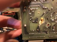
D1 gave me funny readings. Sometimes ok sometimes not. When I took out the controller PCB it became clear that something was wrong there (Had I taken it out on the first day I would have seen this immediately).
Anyway, I replaced the D1, reinforced the trace, brushed with isopropanol, put it together and finally it works as intended.
Many thanks to Steve for his help!
It was very useful and helped me to understand the circuit better.
This forum is awesome because of such people.
Many thanks!
I checked first the R12 again. They can be disconnected from the rest of the circuit by switching CV/CI switch to CI position. In that case R12 measures 33k as it should. This resolves also the question of C3 leakage.
So what else is there? D1 was always a suspect but I measured it in situ and it looked ok (a spoiler I know).
At this stage I started checking whether there are any dead output transistors. Simple checks of diode behaviour between B,C and E have not shown anything suspicious.
I was clueless at this stage but I started putting it apart and now with better access to everything I have decided to check some resistances and especially diodes around the op amps again.
D1 gave me funny readings. Sometimes ok sometimes not. When I took out the controller PCB it became clear that something was wrong there (Had I taken it out on the first day I would have seen this immediately).
Anyway, I replaced the D1, reinforced the trace, brushed with isopropanol, put it together and finally it works as intended.
Many thanks to Steve for his help!
It was very useful and helped me to understand the circuit better.
This forum is awesome because of such people.
Many thanks!
Attachments
One thing to check is whether the output voltage does indeed rise or whether only the voltage indication rises. Two different areas of possible failure. From the very first post I get the impression that the output voltage does fall as required.
Jan
Jan