I’m fixing a broken guitar amp for fun, I found it cheap.
To give you an idea, it is a early 2000s reissue of the Carlsbro TC60 (https://el34world.com/charts/Schematics/files/Carlsbro/Carlsbro_60tc.pdf).
But my question is more general: what happens when one tube in push-pull configuration is 50% below specification value (low transconductance, higher anode resistance). Do we expect this to draw significantly more current from the power supply and blow fuses?
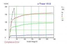
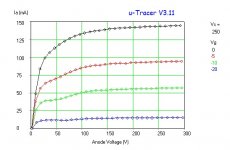
Here are the tracers of the two EL34 tubes
To give you an idea, it is a early 2000s reissue of the Carlsbro TC60 (https://el34world.com/charts/Schematics/files/Carlsbro/Carlsbro_60tc.pdf).
But my question is more general: what happens when one tube in push-pull configuration is 50% below specification value (low transconductance, higher anode resistance). Do we expect this to draw significantly more current from the power supply and blow fuses?
Here are the tracers of the two EL34 tubes
- The good tube! My max current is 200mA so hit compliance with g1=0. This tube is running at about 80% of specification transconductance
- The second tube is the poor tube. Even g1=0 is below 200mA which is really rather low for an EL34. This is operating at around 40% of specification transconductance.
Attachments
No, we expect exactly the opposite.Do we expect this to draw significantly more current from the power supply and blow fuses?
Looks like it is passing too much current so will likely blow the fuse.
Try removing the duff valve and see if it still blows the fuse.
Try removing the duff valve and see if it still blows the fuse.
Thanks for the advice folks.
TG that makes sense, because max power is drawn then both are biased correctly and it’s unlikely one tube can draw so much current as to blow the fuse. At least not these tubes because I know the IV curve.
Nigel, OK going to remove the tubes and try and find the problem. Fuse only blows when high voltage is turned on; heaters are fine.
If it still blows with valves removed could be a power supply fault like diodes or smoothing caps.
Forgot to say, without tubes the fuse does not blow. Will check power supply components anyway. I have already checked power transformer is fine. Will check HT to anodes.
If it doesn't blow without tubes, the excess current is passing through them (no short elsewhere).
A leaking coupling cap will cause excess current through the EL34, causing redplating and then blow the fuse.
You can check if the dc voltage on EL34 socket pin 5 (g1) is positive (or not negative enough). Do this without the EL34's.
It doesn't always show up. I had it with a guitar amp one time that the EL34's wore out quickly, they showed signs of overheating (crackly, warped base). checked out fine one the bench.
Replaced the coupling caps. Happy customer.
!!Be carefull measuring live voltages!!
Old power tubes may encounter current avalance, usually ending up in redplating.
Test the amp withe a new matched pair and see if problems disappear.
Test the amp withe a new matched pair and see if problems disappear.
If the bias is fixed adjustable bias, and there is anything wrong with that bias circuit, and you put new tubes in, you can damage the new tubes.
And, if the bias is self bias, individual or combined, if the bypass cap shorts, it will cause large current in one or both tubes accordingly.
And, as already mentioned, a leaky coupling cap causes high current in the tube too.
Find the cause of the problem first, if possible, before stressing a set of new tubes.
THE fault might be in the tubes. New tubes - problem goneIf the bias is fixed adjustable bias, and there is anything wrong with that bias circuit, and you put new tubes in, you can damage the new tubes.
And, if the bias is self bias, individual or combined, if the bypass cap shorts, it will cause large current in one or both tubes accordingly.
And, as already mentioned, a leaky coupling cap causes high current in the tube too.
Find the cause of the problem first, if possible, before stressing a set of new tubes.
Indeed, the fault might be in the tubes.
Or might be in the bias circuit.
Or might be in a coupling cap.
Randomly replacing components is one way of troubleshooting, but not the best.
Measure first and analyse.
Or might be in the bias circuit.
Or might be in a coupling cap.
Randomly replacing components is one way of troubleshooting, but not the best.
Measure first and analyse.
Very true. Except possibly in the simplest of cases, tubes are notoriously prone to burn out, and if a power tubes have suffered grid current avalanche they tend to repeat this. Replacing both tubes with a matched new pair is a timesaving and simple test if one can watch the amp and turn off in the event of current rising.Indeed, the fault might be in the tubes.
Or might be in the bias circuit.
Or might be in a coupling cap.
Randomly replacing components is one way of troubleshooting, but not the best.
Measure first and analyse.
Hi Peter,
I posted the IV curve of both tubes. They look OK but one is quite poor; significantly lower than the other.
I need to revise my last statement: fuses are blow with or without tubes and only with HT on.
I guess this isolates the issue to the power supply diodes, capacitors or resistors. I will check one by one.
Some amplifiers use caps that have a lower voltage rating than the unloaded B+ voltage.
Over time, the underrated caps can fail and short. And that is bad for the rectifiers, tube or solid state.
The most often causes of unloaded B+ are:
Slower warm up of output tubes versus rectifier tubes and/or solid state diodes,
Weak old output tubes,
And Hot Starts (caused by power mains momentary interruption, in your amplifier with the standby switch in the ON position).
Last edited:
If those 50uf caps in the HT filter are indeed put in series without the equalizing resistors as shown in the schematics, I would be very amused if some of them didn't went south.
TG,
Good catch!
boyfarrell,
The designer saved some money by not having any bleeder resistor(s)!
Fix two problems at once . . .
Put individual equalizing resistor across each of those 4 electrolytic caps.
Safety First!
Prevent the "Surviving Spouse Syndrome".
Good catch!
boyfarrell,
The designer saved some money by not having any bleeder resistor(s)!
Fix two problems at once . . .
Put individual equalizing resistor across each of those 4 electrolytic caps.
Safety First!
Prevent the "Surviving Spouse Syndrome".
Last edited:
I’m actually working on the reissue of this amp, and it does have those bleed resistors!
I cannot find a schematic anywhere online, I have emailed Carlsbro, but nothing yet.
It’s a full wave rectifier, with two pairs of two 250V 333uF in series, with bleed resistors in parallel with each cap. Obviously using lower voltage rating by putting them in series. This feeds the power tubes via some 1k 5W resistors, and then enters more smoothing RC components, this time they are 450V 22uF, five (!) in parallel, which feeds the pre-amp tubes. I’ve detached the PCB today and I’ve being tracing it a bit.
Was wondering if I should get an ESR meter for testing caps?
Last edited by a moderator:
- Home
- Amplifiers
- Tubes / Valves
- Failing EL34 tube in push-pull blowing fuses?