Good morning to the group,
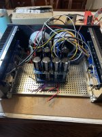
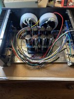
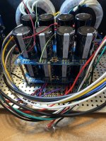
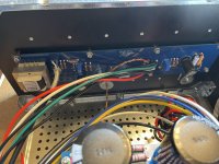
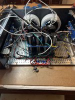
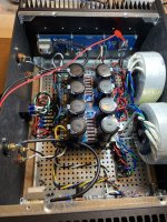
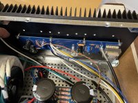
I’m a newer builder and reached another challenge there perhaps someone can share some of their expertise. My latest project is the First Watt F6. I built it and now am in the final stages of biasing the channels. With (2) meters clipped the source resistors and(2) others connected on the speaker outputs, I thought I was golden because I kept watching my heat sink temps were as I ran the bias up and we’re just nicely warm, never hot at 47*C. As I continued to raise the bias, finally stopping at 565/575mv and offset set @ +\- 1-2mv. Everything seemed nice and stable. So after a few different days of monitoring the bias and offset remaining fairly stable. I connected some test speakers, there’s no hum or noise so I played some music. It sounded good. It’s when I went to take my test equipment off I noticed the plastic on my test leads on both channels Source Resistors was literally melted. Shame on me for not noticing sooner and not checking the mosfets sooner. I just assumed if the heatsink is cool, so is what is attached to it. I got my infrared and started shooting temps on the mosfets. THEY ARE HOT, very hot @ 69*C. I immediately backed down the bias on both channels to around 350mv. After some time i checked temps again and they are still super at at almost the same temp 68/69C. Even the hold down washers are extremely hot. I never noticed this on the F5T or Aleph J amps and I will check those this weekend. I checked to be sure my screws were tight and they are. It almost seems like I’m not transferring the heat from the mosfets to the heatsinks. Is that Possible? I guess I should ask, do I have an issue to address?
I’m a newer builder and reached another challenge there perhaps someone can share some of their expertise. My latest project is the First Watt F6. I built it and now am in the final stages of biasing the channels. With (2) meters clipped the source resistors and(2) others connected on the speaker outputs, I thought I was golden because I kept watching my heat sink temps were as I ran the bias up and we’re just nicely warm, never hot at 47*C. As I continued to raise the bias, finally stopping at 565/575mv and offset set @ +\- 1-2mv. Everything seemed nice and stable. So after a few different days of monitoring the bias and offset remaining fairly stable. I connected some test speakers, there’s no hum or noise so I played some music. It sounded good. It’s when I went to take my test equipment off I noticed the plastic on my test leads on both channels Source Resistors was literally melted. Shame on me for not noticing sooner and not checking the mosfets sooner. I just assumed if the heatsink is cool, so is what is attached to it. I got my infrared and started shooting temps on the mosfets. THEY ARE HOT, very hot @ 69*C. I immediately backed down the bias on both channels to around 350mv. After some time i checked temps again and they are still super at at almost the same temp 68/69C. Even the hold down washers are extremely hot. I never noticed this on the F5T or Aleph J amps and I will check those this weekend. I checked to be sure my screws were tight and they are. It almost seems like I’m not transferring the heat from the mosfets to the heatsinks. Is that Possible? I guess I should ask, do I have an issue to address?
Attachments
-
 AAC45857-0279-4F2E-B224-A1D6232C34CB.jpeg939.6 KB · Views: 172
 -
 128ED44D-0A09-47F6-9243-DDAA1318663B.jpeg921.3 KB · Views: 160
 -
 9C67B777-1080-4DBC-9B4F-45B1168DB21B.jpeg892.3 KB · Views: 153
 -
 8D8ED766-C60C-4B7E-AA10-06A3C28EC6CF.jpeg881.1 KB · Views: 162
 -
 6C73E74A-11D2-46AB-BB7E-5661C192C10F.jpeg679.1 KB · Views: 154
 -
 BF299213-056D-4C5D-B89B-F342CFE5780D.jpeg660.1 KB · Views: 160
 -
 7C476357-5607-48FA-875D-2A28063901CA.jpeg661.3 KB · Views: 162
 -
 BECEB41B-C2DC-420F-A397-DD29D3303443.jpeg428.1 KB · Views: 159
 -
 81A52B2E-282B-4548-A879-692C4F5FD3CA.jpeg759.6 KB · Views: 188
Did you used heat transfer grease (here it is known as siliconed grease, white 8n color). Is there any isolating element between semicon tab and heat sink? Which is the thickness? Material?
MOSFET's has positive tempco, so they usually don't runaway.
MOSFET's has positive tempco, so they usually don't runaway.

I did not use any grease. I used silicone pads, unfortunately not the keratherm ones sold in the store, but some I had on hand. I don’t know the exact thickness. They do seem thicker than the keratherm. This is the only amplifier where I used a different insulating pad instead of the stores.
With the heatsink size you have, and assuming voltage rails of +/- 24VDC, and optimal bias of (500 to 600mV/0.47 ohms = 1.1 A), you might have a problem.
Check every single pin on the MOSFETS and see if there is any short to Ground. Remember the back of the MOSFET is also connected to the Drain pin, as such you should make sure the insulation between the MOSFET and heatsink is not broken (it should not be electrically conductive, but it should be thermally conductive).
Agree with Osvaldo’s and Aleksander’s line of thinking…
Best,
Anand.
I was wondering about that and ordered some Mica yesterday.silicone pads - no go for FW amps
change that for mica+goop
The case is the deluxe 4U and the heatsink that Congress with it. I will check for conductivity when I get home.With the heatsink size you have, and assuming voltage rails of +/- 24VDC, and optimal bias of (500 to 600mV/0.47 ohms = 1.1 A), you might have a problem.
Check every single pin on the MOSFETS and see if there is any short to Ground. Remember the back of the MOSFET is also connected to the Drain pin, as such you should make sure the insulation between the MOSFET and heatsink is not broken (it should not be electrically conductive, but it should be thermally conductive).
Agree with Osvaldo’s and Aleksander’s line of thinking…
Best,
Anand.
Just for the convenience, I’m a big fan of the Keratherm from the diy audio store.silicone pads - no go for FW amps
change that for mica+goop
Just for the convenience, I’m a big fan of the Keratherm from the diy audio store.
of course that Keratherm is better
I usualy use those gray gum rectangles (I have many of them rescued from dismantled PC power supplies) but also add thermal compound, aka grease.
no good (enough), and thermal paste is doing nothing with gray gums, nor it's making it better

Hey guys, thanks to all of your suggestions and recommendations.
As it turned out the silicone pads I used from my stash were obviously not liked by my mosfets in the F6. I had some Mica pads and paste and it made a huge difference. I am now biased at 558/560mv and -.2/-.1.8 ofs and the hosts they get are 58/59*C on the device and the heatsink is about 46*C. Bright is down and connected it up and it sounds fantastic. I can imagine it’ll probably take sober time for a real burn in but am very happy to this point. Thanks again.
As it turned out the silicone pads I used from my stash were obviously not liked by my mosfets in the F6. I had some Mica pads and paste and it made a huge difference. I am now biased at 558/560mv and -.2/-.1.8 ofs and the hosts they get are 58/59*C on the device and the heatsink is about 46*C. Bright is down and connected it up and it sounds fantastic. I can imagine it’ll probably take sober time for a real burn in but am very happy to this point. Thanks again.
I segond torqueing them. But I’d consider desoldering the mosfets too, and torque then them to the sink before soldering them back into the board. You should be able to get the temp between sink and fet more alike.Hey guys, thanks to all of your suggestions and recommendations.
As it turned out the silicone pads I used from my stash were obviously not liked by my mosfets in the F6. I had some Mica pads and paste and it made a huge difference. I am now biased at 558/560mv and -.2/-.1.8 ofs and the hosts they get are 58/59*C on the device and the heatsink is about 46*C. Bright is down and connected it up and it sounds fantastic. I can imagine it’ll probably take sober time for a real burn in but am very happy to this point. Thanks again.
Reason being, the silicone pads were likely thicker than what you are using now. Also, Mighty recipe being torque first, then solder. If you torque now you risk straining the mosfet legs and or them making uneven contact with the sink, worst case cutting the pads and making electrical contact between the fets and the sink.
Of course, if the new pads are just as thick as the sillycone valley pads, you are home free.
Hugz and kissez,
Baby V
I've always just snugged them but it is a good idea to touch the leads with the soldering gun to take the strain off of them after you have tightened things. If the MOSFETs have twisted at all, you will see the leg move slightly when you melt the solder at each solder point. Do it twice for good measure on each MOSFET.
"Some I had on hand" rubber insulating washers can be impressively bad and have no business anywhere near class A anything. Been there.
- Home
- Amplifiers
- Pass Labs
- F6 Mosfets running too hot?