Thanks Patrick.
I think you mean one 24V DPDT or DPST relay can handle two channels?
In a stereo power supply (as opposed to dual mono), would one be able to get away with a single SPST by tying together the L&R speaker negatives?
I think you mean one 24V DPDT or DPST relay can handle two channels?
In a stereo power supply (as opposed to dual mono), would one be able to get away with a single SPST by tying together the L&R speaker negatives?
> I think you mean one 24V DPDT or DPST relay can handle two channels?
No.
DP because you can switch both outputs of ONE amp at the same time.
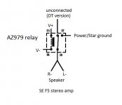
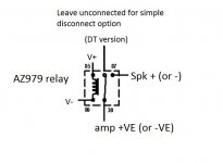
DT because you can choose to disconnect (series) or short circuit (shunt) the amp output in case of fault.
Most people use series, so the relay is in the signal path.
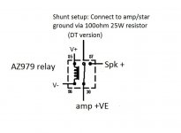
I use shunt, because it is non-invasive. But a safty trip will no doubt kill all your output devices.
> In a stereo power supply (as opposed to dual mono), would one be able to get away with a single SPST by tying together the L&R speaker negatives?
Of course NOT.
We have balanced amplifiers here.
Patrick
No.
DP because you can switch both outputs of ONE amp at the same time.
DT because you can choose to disconnect (series) or short circuit (shunt) the amp output in case of fault.
Most people use series, so the relay is in the signal path.
I use shunt, because it is non-invasive. But a safty trip will no doubt kill all your output devices.
> In a stereo power supply (as opposed to dual mono), would one be able to get away with a single SPST by tying together the L&R speaker negatives?
Of course NOT.
We have balanced amplifiers here.
Patrick
> In a stereo power supply (as opposed to dual mono), would one be able to get away with a single SPST by tying together the L&R speaker negatives?
Of course NOT.
We have balanced amplifiers here.
Ok, not for balanced amp. Will it work for SE F5?
Attachments
> I think you mean one 24V DPDT or DPST relay can handle two channels?
No.
DP because you can switch both outputs of ONE amp at the same time.
DT because you can choose to disconnect (series) or short circuit (shunt) the amp output in case of fault.
Most people use series, so the relay is in the signal path.
I use shunt, because it is non-invasive. But a safty trip will no doubt kill all your output devices.
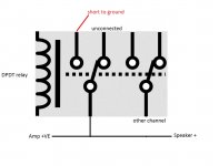
I'm not 100% sure on what you mean by shunt. Perhaps like this?
Attachments
Post#823 is in theory possible, but you are using common Gnd for both stereo channels.
This people do in headphones.
I don't understand your motivation.
You want to save the cost of one relay ?
All the relays you have drawn above are SPDT, not DPDT.
File:Relay symbols.svg - Wikipedia, the free encyclopedia
Patrick
This people do in headphones.
I don't understand your motivation.
You want to save the cost of one relay ?
All the relays you have drawn above are SPDT, not DPDT.
File:Relay symbols.svg - Wikipedia, the free encyclopedia
Patrick
Can I use 12v SPDT? I have two which are 12V.
I think you would leave 87A (center) unconnected
Attachments
Post#823 is in theory possible, but you are using common Gnd for both stereo channels.
This people do in headphones.
I don't understand your motivation.
You want to save the cost of one relay ?
All the relays you have drawn above are SPDT, not DPDT.
File:Relay symbols.svg - Wikipedia, the free encyclopedia
Patrick
Not really concerned about the cost of one relay ($5) 🙂
Just an exercise in the possible. Plus I find fewer parts more elegant.
> I think you mean one 24V DPDT or DPST relay can handle two channels?
No.
DP because you can switch both outputs of ONE amp at the same time.
DT because you can choose to disconnect (series) or short circuit (shunt) the amp output in case of fault.
Most people use series, so the relay is in the signal path.
I use shunt, because it is non-invasive. But a safty trip will no doubt kill all your output devices.
Patrick
Is this what you mean by short circuit (shunt)? Would disconnecting the power supply to the amp also work?
Attachments
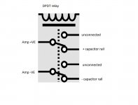
Shunt means short circuiting the positive and negative terminal using the NC contact of the relay.
Amp will NOT work in any case if auxillary supply is disconnected.
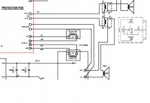
I suggest you do use the series type protection, as published.
Patrick
Amp will NOT work in any case if auxillary supply is disconnected.
I suggest you do use the series type protection, as published.
Patrick
John,
This is most excelllent for a first-time effort.
Many congradulations.
I cannot wait to see how perfect your final article will look. 🙂
Keep us posted.
Patrick
This is most excelllent for a first-time effort.
Many congradulations.
I cannot wait to see how perfect your final article will look. 🙂
Keep us posted.
Patrick
John,
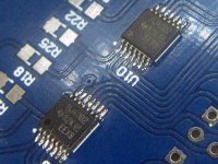
I was worried about my lack of SMD experience as well when I started to populate the protection board. But like you said, the right tools (flux is so important) and some patience goes a long way.
Good luck and let us know how it turns out!
I was worried about my lack of SMD experience as well when I started to populate the protection board. But like you said, the right tools (flux is so important) and some patience goes a long way.
Good luck and let us know how it turns out!
Thanks Patrick and Greg,
Like you said Greg patience and working slowly is key, I’ll update once I have the protection board up and running.
BTW for those that are still after auxiliary transformers, I got a custom made version from SUMR (Canada) to spec, core banded, epoxy filled centre with 650mm secondary leads (will reach the protection board without re-termination). $45USD.
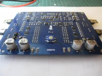
I made good progress this weekend, if I hadn’t ordered the wrong 120kohm resistors instead of the 120ohm I would of found time to test.
I did a diode test, the bi-coloured LED will only aluminate red, I assume this is because of the current state of the circuit setting?
Some progress pics... and yes I need to clean that flux off!
I did a diode test, the bi-coloured LED will only aluminate red, I assume this is because of the current state of the circuit setting?
Some progress pics... and yes I need to clean that flux off!
Attachments
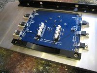
You should make some square-on shots.
Then I can also use them.
Isn't it gorgeous layout ?
Very well sone. 🙂
Patrick
Then I can also use them.
Isn't it gorgeous layout ?
Very well sone. 🙂
Patrick
- Home
- Amplifiers
- Pass Labs
- F5X -- the EUVL Approach