I am interested in a group buy for Toshiba MOSFETs. We should start a GB thread for this.
I have been asked by PM about sourcing MOSFETs.
You probably all know that Toshiba is stopping all audio devices, MOSFETs and JFETs alike.
The only open source that is known to have sufficient quantities for NNPP match is, as mentioned before, ZhouFang.
It has also been discussed before that his matching is not exactly at F5X operating conditions.
So if you do not wish to purchase from Zhou, the only solution right now is to GB and match yourselves.
We ourselves are in the process of acquiring sufficient devices to support future batches of F5X projects.
But it won't be 6 months or so before we are ready, and then only in the context of supporting the project,
and not as separate devices sets for general sales.
Patrick
F5X varient for small heatsink
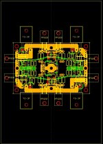
I am working on a variant of Patrick's F5X board that is shrunk to a 2.5" x 3.8" board to be mounted on a 5" x 7" heatsink . Two such heatsinks are attached fin-to-fin to form a heat tunnel, cooled by a very quiet 120 mm fan. Here are images of the layout:
The first image shows the entire heatsink, with the airflow from top-to-bottom (yeah, I know, this is upside-down from normal conventions). The MOSFET placement was carefully chosen for heat distribution. The design is for 100-120 watts dissipation per heatsink.
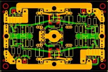
The second image is the PCB. The resemblance to EUVL's layout should be apparent. Due to space restrictions, the 220 ohm feedback resistors are replaced with Caddock MP820's attached to the heatsink.
There are 2 major jumpers (not shown) for the X connections. Without any other jumpers, the board provides an F5X. Two jumpers provide a floating balanced togolopy, (the X's are connected). Two more jumpers activate Nelson's P3 adjustment. And finally, two more jumpers ground everything for initial adjustment or for use as 2 independent unbalanced F5 amplifiers. The jumpers are intended to be made using .1 inch shunts, but soldering is possible.
Balanced input connections are made using a 4 pin header. At the corners are 2 pin headers for connections to the source resistors for initial adjustment.
I am working on a variant of Patrick's F5X board that is shrunk to a 2.5" x 3.8" board to be mounted on a 5" x 7" heatsink . Two such heatsinks are attached fin-to-fin to form a heat tunnel, cooled by a very quiet 120 mm fan. Here are images of the layout:
The first image shows the entire heatsink, with the airflow from top-to-bottom (yeah, I know, this is upside-down from normal conventions). The MOSFET placement was carefully chosen for heat distribution. The design is for 100-120 watts dissipation per heatsink.
The second image is the PCB. The resemblance to EUVL's layout should be apparent. Due to space restrictions, the 220 ohm feedback resistors are replaced with Caddock MP820's attached to the heatsink.
There are 2 major jumpers (not shown) for the X connections. Without any other jumpers, the board provides an F5X. Two jumpers provide a floating balanced togolopy, (the X's are connected). Two more jumpers activate Nelson's P3 adjustment. And finally, two more jumpers ground everything for initial adjustment or for use as 2 independent unbalanced F5 amplifiers. The jumpers are intended to be made using .1 inch shunts, but soldering is possible.
Balanced input connections are made using a 4 pin header. At the corners are 2 pin headers for connections to the source resistors for initial adjustment.
Attachments
There were some discussions about distortion cancellation of the F5X at the build thread.
The original discussion in 2008 (!!!) you can find here.
http://www.diyaudio.com/forums/pass-labs/121228-f5-power-amplifier-24.html#post1538833
Fitzfish and I also stated on a couple of occasions that the measured distortion spectrum does not differ between ground X, floating X, and the H connected (see NP's article on F5 Turbo, the balanced schematics towards the end). However, the floating X or H will allow the circuit to operate with single ended inputs (-Vin connected to Gnd), which is not the case for the grounded X.
Patrick
Hi,
If I have a choice between two match quads of 2sk1530/2sj201
0.265 / 0.265 / 0.265 / 0.265 or
0.350 / 0.350 / 0.350 / 0.350
which, if any, would be better for this project?
If I have a choice between two match quads of 2sk1530/2sj201
0.265 / 0.265 / 0.265 / 0.265 or
0.350 / 0.350 / 0.350 / 0.350
which, if any, would be better for this project?
Assume the numbers are the Vgs different between N and P, I suppose closer is better, i.e. 0.265 / 0.265 / 0.265 / 0.265. Whether there will be audible different between the 2 sets is another story.
You need to show me actual Vgs (also at what current and what Vds) of all 4 MOSFETs in a set, before I can tell you which is better.
Patrick
Patrick
Yes, they are Vgs, matched at 24V and 1.3A (for standard F5). If possible I will test at 2A but was just wondering if all things being equal, would the lower or higher Vgs be advantageous for the F5X.
Are they 2SK1530Y / 2SJ201Y ?
If so I expect the Vgs to be around 2.xxV, and not 0.2xxV.
Patrick
If so I expect the Vgs to be around 2.xxV, and not 0.2xxV.
Patrick
Now I know where these numbers came from.
If I were you I would choose the higher numbers. 🙂
Patrick
If I were you I would choose the higher numbers. 🙂
Patrick
Thanks Patrick.
I have sets from both Zhou and Blues (Who matches at 24V/1.3A). BTW, he as 4 quads left if anyone is interested.
I have sets from both Zhou and Blues (Who matches at 24V/1.3A). BTW, he as 4 quads left if anyone is interested.
EUVL,
Have you listened to Welwyn RC55Y and how would you compare them to PRP. Perhaps they are indistinguishable, just wandering.
Have you listened to Welwyn RC55Y and how would you compare them to PRP. Perhaps they are indistinguishable, just wandering.
Patrick,
You still considering doing a F5X-Turbo down the road, or have you fallen out of favor of the paralleled diode?
You still considering doing a F5X-Turbo down the road, or have you fallen out of favor of the paralleled diode?
I shall do a F5X turbo end of this year after the F5X Preamp.
But I shall do it my way, i.e. without having to use diodes.
😉
Patrick
But I shall do it my way, i.e. without having to use diodes.
😉
Patrick
I look forward to your iteration. I assume it means you have something clever up your sleeve. Why not try an X-ed F5 FE pushing a buffer.
I have many ideas up my sleeve.
Someone else can decide whether they are clever after they have been published. 😉
But one at a time.
Next (public) project is F5X Preamp, as promised.
Patrick
Someone else can decide whether they are clever after they have been published. 😉
But one at a time.
Next (public) project is F5X Preamp, as promised.
Patrick
I shall do a F5X turbo end of this year after the F5X Preamp.
When are you going to release some info on the FX5 Preamp? We are getting very curious.
When the first proto is finished, probably not before end of August.
It comes in 2 cases (one for amp and one for power supply) that match the F5X power amp case.
Circuit similar to the F5X power amp.
With push buttons, remote control, relay source selector and attenuators.
Attenuator uses Caddock MK132 or Vishay S102 resistors.
Enough details for now ?
😉
Patrick
It comes in 2 cases (one for amp and one for power supply) that match the F5X power amp case.
Circuit similar to the F5X power amp.
With push buttons, remote control, relay source selector and attenuators.
Attenuator uses Caddock MK132 or Vishay S102 resistors.
Enough details for now ?
😉
Patrick
- Home
- Amplifiers
- Pass Labs
- F5X -- the EUVL Approach