k , i've just gone through over one hundred 2sk170's and have yet to find but one under 8.00 (7.96) and Bill Fuss is reporting 9's to 10 from his batch , is there a reason for the low idss beyond the fact that NP mentioned 7.0 2sk170 ?
k , i've just gone through over one hundred 2sk170's and have yet to find but one under 8.00 (7.96) and Bill Fuss is reporting 9's to 10 from his batch , is there a reason for the low idss beyond the fact that NP mentioned 7.0 2sk170 ?
I have matched quads and octets in that Idss range, if I can help.
> is there a reason for the low idss beyond the fact that NP mentioned 7.0 2sk170 ?
Of course. For such a simple circuit, nothing is there by chance.
You can use 10mA Idss, or even 14mA, if you want. The circuit will still work.
But a higher front-end bias will mean smaller values of JFET drain resistors, and therefore lower open-loop gain, or less negative feedback.
Patrick
Of course. For such a simple circuit, nothing is there by chance.
You can use 10mA Idss, or even 14mA, if you want. The circuit will still work.
But a higher front-end bias will mean smaller values of JFET drain resistors, and therefore lower open-loop gain, or less negative feedback.
Patrick
Can you comment on the expected changes regarding the Input JFET "Degeneration trick" or does the previously stated formula apply?
thx 😀
thx 😀
> Can you comment on the expected changes regarding the Input JFET "Degeneration trick" or does the previously stated formula apply?
The degeneration still applies but you need to compare the Yfs value at that specific bias current, which you can either measure yourself (for both devices), or use the data sheet values.
Patrick
The degeneration still applies but you need to compare the Yfs value at that specific bias current, which you can either measure yourself (for both devices), or use the data sheet values.
Patrick
> is there a reason for the low idss beyond the fact that NP mentioned 7.0 2sk170 ?
Of course. For such a simple circuit, nothing is there by chance.
You can use 10mA Idss, or even 14mA, if you want. The circuit will still work.
But a higher front-end bias will mean smaller values of JFET drain resistors, and therefore lower open-loop gain, or less negative feedback.
Patrick
These are very difficult to source, the 2sj74s i mean, i got some from AMB labs but they all have IDSS in the high 10mA range.
The matched sets from Spencer are in the same range.
2SK170BL in the 6mA and 7 mA range are easier to find.
Last edited:
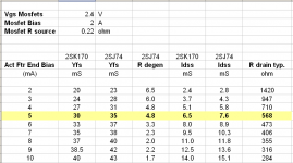
You have to bear in mind that these figures, especially the Yfs, is read from data sheet and hence prone to error.
So use it as guide line only. It is not gospel.
If you want to be really exact, you have to measure the FETs to determine the real values.
There is no short cut, I am afraid.
Patrick
So use it as guide line only. It is not gospel.
If you want to be really exact, you have to measure the FETs to determine the real values.
There is no short cut, I am afraid.
Patrick
These are very difficult to source, the 2sj74s i mean, i got some from AMB labs but they all have IDSS in the high 10mA range.
The matched sets from Spencer are in the same range.
2SK170BL in the 6mA and 7 mA range are easier to find.
I am very sympathetic to anyone doing a balanced build.
I have a large number of match JFETS in EVERY Idss range, even sets already matched for the degeneration difference. I did this for my builds.
Let my know by PM if you need a set of matched Octets, or if you would like two matched Quads.
I used an Octet, and have sent other Octets to other builders, but they are a much more difficult match, as you might imagine.
May I suggest you open a thread at the swap meet forum for your very generous offers.
Most sincere thanks,
Patrick
Most sincere thanks,
Patrick
I have a (150) 2SK170-BL's, and I've matched 50 of them. So far I have been getting a nice range of values with most of them in the 6-9mA range. Hopefully the remaining 100 jfets are nicely distributed as well. Once I get the remaing jfets matched, I can probably help out a few people as well.
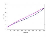
You can see a typical distribution of Idss for a large enough batch (in this case 500) of 2SK170s and 2SJ74s.
The measurements were done in January 2009.
(Blue is 2SJ74.)
http://www.diyaudio.com/forums/solid-state/135154-next-best-thing-2sk389-2sj109-2.html#post1730586
Patrick
.
The measurements were done in January 2009.
(Blue is 2SJ74.)
http://www.diyaudio.com/forums/solid-state/135154-next-best-thing-2sk389-2sj109-2.html#post1730586
Patrick
.
Attachments
Last edited:
May I suggest you open a thread at the swap meet forum for your very generous offers.
Most sincere thanks,
Patrick
Not interested in a business, just trying to help your builders.
None the less, I'll post something.
Last edited:
Updated Case Parts Photos
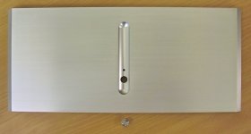
We got the prototype case parts back after some revisions and re-finishing.
We shall post them part by part today.
Assembled later in the week.
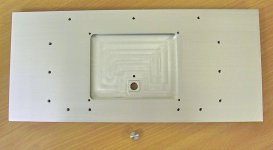
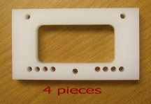
Starting with the front panel.
Patrick
.
We got the prototype case parts back after some revisions and re-finishing.
We shall post them part by part today.
Assembled later in the week.
Starting with the front panel.
Patrick
.
Attachments
Last edited:
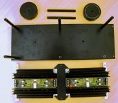
Followed by the cradle, transformer feet, regulator heat sink & PCB, and associated parts.
The plates joining the heat sink will get a much better looking (in design) revision later.
The heat sinks will get re-anodised (to all black).
And the O-Rings will get white silicone.
.
The plates joining the heat sink will get a much better looking (in design) revision later.
The heat sinks will get re-anodised (to all black).
And the O-Rings will get white silicone.
.
Attachments
Last edited:
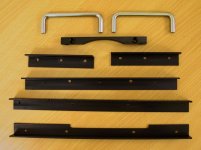
The structural parts :
machined extrusion angles, cross bars, handles, ...
.
machined extrusion angles, cross bars, handles, ...
.
Attachments
Last edited:
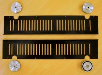
Main heat sink (Conrad MF35-151) feet and bottom covers.
.
.
Attachments
Last edited:
- Home
- Amplifiers
- Pass Labs
- F5X -- the EUVL Approach