Nice testing 😉
Was trying to find our when you are likely to get case today....independent of Patrick's justifiable forays...
Things are going to anodizer next week and i don't expect them to take more than a week.
So cases are very close to getting shipped.
Was trying to find our when you are likely to get case today....independent of Patrick's justifiable forays...
Things are going to anodizer next week and i don't expect them to take more than a week.
So cases are very close to getting shipped.
Last edited:
I did the X connection and tried to feed the amp with some sine wave in balanced format but I got nothing from the output. I checked the output from my Focusrite Scarlet with scope and saw a good balanced signal coming out but when connected to the amp no output.
Is there some trick perhaps that I don’t understand when measuring/connecting? Now I’m afraid I have damaged something.
Bias currents were spot on 2 A in every ”corner” and dc offset only few mV.
Is there some trick perhaps that I don’t understand when measuring/connecting? Now I’m afraid I have damaged something.
Bias currents were spot on 2 A in every ”corner” and dc offset only few mV.
Attachments
Last edited:
I did the X connection and tried to feed the amp with some sine wave in balanced format but I got nothing from the output. I checked the output from my Focusrite Scarlet with scope and saw a good balanced signal coming out but when connected to the amp no output.
Is there some trick perhaps that I don’t understand when measuring/connecting? Now I’m afraid I have damaged something.
Bias currents were spot on 2 A in every ”corner” and dc offset only few mV.
Morde,
The X is joined in the middle, but does not touch ground....see closely the drawing Patrick posted. electrically is the same...X, H, U....

So I did some calculations from your single ended measurements.
One side has H2 at -96.8dB, the other -99.1dB.
At the balanced output, they will cancel to -110dB H2.
😉
Patrick
One side has H2 at -96.8dB, the other -99.1dB.
At the balanced output, they will cancel to -110dB H2.
😉
Patrick
A word of warning upfront, even though seemingly obvious.
To test the amp in fully balanced mode, you will need a signal source which is fully symmetrical.
And I would start with 0.2V per phase, 1kHz first.
If you only have a scope, then make sure you only measure one phase (whether input or output) per probe relative to Gnd.
If you want to measure distortion across the balanced outputs, please make absolutely sure your analyser has truly differential inputs.
Many so-called balanced sound cards are not truely differential.
You can do a lot of damage if you make a seemingly harmless but incorrect connection to your test equipment.
If in doubt, use a differential probe.
DIY Balanced / Differential oscilloscope probes?
CeeVee has promised to make a kit available to any (present or previous) GB subscribers purely as a service.
Mechanical parts and PCB only, others are standard Mouser / Digikey.
Patrick
There were some questions about the X connection.
I guess the best is to use the one published by Nelson :
http://www.firstwatt.com/pdf/art_f5_turbo.pdf
(page 15)
You can call it X with a dot in the middle, or an H.
Either can be done on the PCB easily.
😉
Patrick
I guess the best is to use the one published by Nelson :
http://www.firstwatt.com/pdf/art_f5_turbo.pdf
(page 15)
You can call it X with a dot in the middle, or an H.
Either can be done on the PCB easily.
😉
Patrick
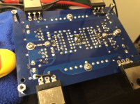
Due to some confusion in my measurements that gave me the wrong assumption that something was damaged in my build, I had to do some extensive measurements for the JFETs and MOSFETs only to find out that there was no fault. 😀
Here’s some report what you are able to measure if you boubt a faulty device.
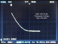
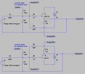
JFETs can be measured even when they are soldered to the pcb. Note that the MOSFETs must not be installed. The X point of the JFETs needs to be floating and then you connect 1k (R3/R8)and 100k (R4/R9) resistors and scope channels according to the picture 1 attached. The dc offset part (R1,2,6,7) can be omitted if your signal source has dc offset functionality. You should then be able to plot in X-Y mode of the scope a curve that should correspond to the JFETs Vgs/Id curve. See pic 2 for example.
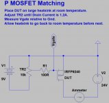
The MOSFETs Vgs at targeted rail voltage and bias current can be measured according to pic 3. This is presented somewhere in the UDNeSS thread as well. For the F5X you want to have 16V and 2 A. Remember to change the connection for N channel device.
Thanks to Patrick for the measuring guidelines and ideas. I couldn’t have done it by myself.
After successful measurement results I was confident that my circuitry was intact and I could proceed with re-soldering once again the output devices into place. After checking bias currents and dc offsets I went on measuring some distortions.
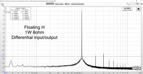
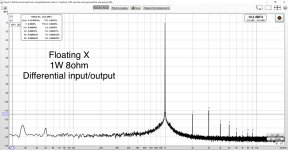
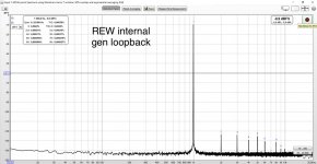
My distortion measurement setup is simply a Focusrite Scarlet 2i connected to a laptop that is running REW software. Loopback measurement using balanced in => balanced out connections is presented in pic 4.
Pic 5 is my F5X in floating X configuration and pic 6 the same with floating H config. Measurements were done in balanced mode with 1W/8ohm load. Very similar results, but the H is a tiny bit better with second harmonic. Amazingly low distortion from a class A diy amp. 🙂
Here’s some report what you are able to measure if you boubt a faulty device.
JFETs can be measured even when they are soldered to the pcb. Note that the MOSFETs must not be installed. The X point of the JFETs needs to be floating and then you connect 1k (R3/R8)and 100k (R4/R9) resistors and scope channels according to the picture 1 attached. The dc offset part (R1,2,6,7) can be omitted if your signal source has dc offset functionality. You should then be able to plot in X-Y mode of the scope a curve that should correspond to the JFETs Vgs/Id curve. See pic 2 for example.
The MOSFETs Vgs at targeted rail voltage and bias current can be measured according to pic 3. This is presented somewhere in the UDNeSS thread as well. For the F5X you want to have 16V and 2 A. Remember to change the connection for N channel device.
Thanks to Patrick for the measuring guidelines and ideas. I couldn’t have done it by myself.
After successful measurement results I was confident that my circuitry was intact and I could proceed with re-soldering once again the output devices into place. After checking bias currents and dc offsets I went on measuring some distortions.
My distortion measurement setup is simply a Focusrite Scarlet 2i connected to a laptop that is running REW software. Loopback measurement using balanced in => balanced out connections is presented in pic 4.
Pic 5 is my F5X in floating X configuration and pic 6 the same with floating H config. Measurements were done in balanced mode with 1W/8ohm load. Very similar results, but the H is a tiny bit better with second harmonic. Amazingly low distortion from a class A diy amp. 🙂
Attachments
-
 AC0B0C3B-427A-4D1A-A9BB-A06706CCF14A.jpeg255.2 KB · Views: 412
 -
 8D314A0F-573A-419F-8FF9-FF53AA98874B.jpeg259.3 KB · Views: 853
 -
 B2A87DAF-AFCC-44F5-94E8-62C40F02A4B6.jpeg112 KB · Views: 907
 -
 20CC7233-B8A9-465B-8AEC-9505029C190A.jpeg118.3 KB · Views: 1,059
 -
 970847ED-576E-4618-8F6E-25B72B0FEAEC.jpeg559.9 KB · Views: 1,064
 -
 3D2043E3-8BAB-4188-BBE8-B2693EAA1B09.png27.9 KB · Views: 1,102
> but the H is a tiny bit better with second harmonic
As it should.
And the even lower H2 than H3 is the evidence of the level of device matching.
😉
Patrick
As it should.
And the even lower H2 than H3 is the evidence of the level of device matching.
😉
Patrick
For those who want to do the testing step by step, you can test the entire front end as in the attached Spice file.
The only thing not installed are the MPC74's and the Toshiba MOSFETs.
You will need to add a 390R resistor to the cross member of the "H".
And you need a balanced signal source of 0.3V (per phase) 1kHz.
Then check V1,2,3,4 and compare with the spice file results.
Once that is done, you only need to put in the MOSFETs and adjust bias / DC offset.
Patrick
.
Attachments
Does anyone have the BoM for the protection board in spreadsheet format please?
It's a pain trying to do it from a pdf!
It's a pain trying to do it from a pdf!
I showed you my LM4780's in post #1272.
A team member in HK wants to have a summer amp to go with his F5X Pre.
(HK summer is 35°C. You need air con, and the F5X adds to the air-con load.)
So I propose to use the same LM4780 inverted.
Here is the result (photo is from earlier, unfunished state).
Case is adapted from the F5X Pre.
🙂
Patrick
.
Attachments
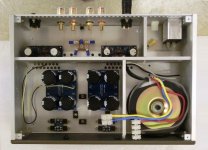
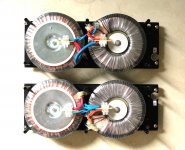
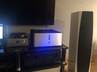
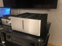
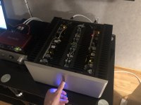
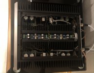
The First music track (Tool - Pneuma) has been played with my F5X! 🙂 Dead silent background without any noise.
Still need to measure and adjust bias currents since it seems to be running a bit hot now @~1.9A.
I attached a couple of quick and dirty photos.
Thanks a lot Patrick and Carlos for making this happen!
Still need to measure and adjust bias currents since it seems to be running a bit hot now @~1.9A.
I attached a couple of quick and dirty photos.
Thanks a lot Patrick and Carlos for making this happen!
Attachments
- Home
- Amplifiers
- Pass Labs
- F5X -- the EUVL Approach - The Build Thread