We don't publish matching data.
Never did, never will.
Only to say that we have a very large pool (>1000 FETs) to match from.
And we build our own matching equipment to guarantee the required long term repeatability.
But below is a random set from this last GB.
The columns are Vgs at 2A, Yfs at 2A for K1530 and J201 respectively.
Data are derived from 2000 measurement points from the curve tracer, then fitted by a 6th order polynomial.
Vgs well within 10mV, Yfs within 3% for each channel.
You will not find a commercial vendor who can match this.
Especially those using a hobby USB curve tracer in pulse mode.
2.280 4.20 2.281 4.30
2.282 4.18 2.282 4.30
2.280 4.33 2.284 4.24
2.282 4.27 2.288 4.32
Patrick
Thanks, the data is good enough.
With these parameters so close, clearly tight matching The source resistor becomes critical.
Thanks
Btw, question but not for you. Somewhere here in the 600+ message I read about the SumR transformers. 500VA coils on 600VA capable torus (Larger to reduce magnetostriction humming). Does the transformer have a standard part number (in this case it will be cheaper). ?
Thanks
Stefano
2 x 15 V or 2 x 16 V
Are the following transformer specs right?
2x115V primary, 2x 15V secondary, electrostatic screen, 500VA core, Max dims D= 150mm h= 75mm. I will be in shenzhen in early Jan for a conference and I am going to get some made for myself?
Sorry, can someone point me to a schematic/description/BOM of the protection board from this last GB?
Somehow can't find it in the thread
Somehow can't find it in the thread
Just a question:
Why are the PSU caps on the heatsinks?
This is the hottest spot in the enclosure, and the heat will reduce the life time of the caps even high temp. versions are used.
Why are the PSU caps on the heatsinks?
This is the hottest spot in the enclosure, and the heat will reduce the life time of the caps even high temp. versions are used.
http://xen-audio.com/documents/f5x/130223 Protection Board F5X Chpt 1.pdf
F5X -- the EUVL Approach - The Build Thread
F5X -- the EUVL Approach - The Build Thread
F5X -- the EUVL Approach - The Build Thread
If your browser adds www in front of xen-audio, you need to remove it for the link to work.
Please take time to read the build thread.
All information are here, lots of them.
Merry Christmas,
Patrick
F5X -- the EUVL Approach - The Build Thread
F5X -- the EUVL Approach - The Build Thread
F5X -- the EUVL Approach - The Build Thread
If your browser adds www in front of xen-audio, you need to remove it for the link to work.
Please take time to read the build thread.
All information are here, lots of them.
Merry Christmas,
Patrick
> Why are the PSU caps on the heatsinks?
They are actually at the coolest place inside the enclosure.
The regulator heatsinks are just as hot.
And at <60°C, they will last many thousands of hours.
How many hours do you listen per week, 10 ?
Patrick
They are actually at the coolest place inside the enclosure.
The regulator heatsinks are just as hot.
And at <60°C, they will last many thousands of hours.
How many hours do you listen per week, 10 ?
Patrick
OK, thanks, just asking, BTW very nice amp.
THX for sharing this fantastic design.
Merry Christmas,
rooka
THX for sharing this fantastic design.
Merry Christmas,
rooka
By the way, if you want to drive bigger relays with the smd relay drivers, you could replace the 2n7002 mosfet with the Si2318CDS mosfet. This has a lower rds on, and so can handle higher loads. Similarly the AOT66920L could be used as a replacement for the irf610 for the same reason.
I've started to assemble the control/protection board and I noticed there is something unclear about some resistor values (at least for me). For example R32_L/R values are marked 2.0k in the BOM (but also 2.7k on the comment column?). Also I can see in NicMac's build picture here (post #449) that he has used value 2.7k. So is it 2.0k or 2.7k for the rev. 4 boards? Sorry if this has been discussed earlier in this thread.
Also for R33_L/R, R34_L/R and R41 there are some differences between "Description", "Comment" and "Digi-Key part number" columns in the BOM.
Also for R33_L/R, R34_L/R and R41 there are some differences between "Description", "Comment" and "Digi-Key part number" columns in the BOM.
See post #1247.
Nic complained his does not trigger.
This has been explained in detail in the thread and the values revised.
The small differences between description, comment & digikey no. were due to availability at the time.
Exact values not critical.
Please take time to understand how everything works, including the protection board.
A lot of effort has been put into explaining.
Once you understand it will answer a lot of those questions automatically.
It is part of the DIY experience, not just solder and power up.
Take your time and enjoy the journey.
Happy New Year,
Patrick
Yes, it is clearly written in the pdf description how the values R32/33/34 affect. I've been too enthusiastic to get the board working, need to cool down a bit. 😉
Happy New Year to all!
Happy New Year to all!
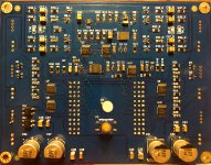
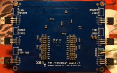
Yes! The most frightening part (for me) of the project is finished. The protection board is now soldered and tested and it seems to work as it should. 🙂 I was very unsure about soldering the TSSOP devices but managed to pull it of by applying too much solder at first to the pins and then removing the excess with solder wick.
Attachments
Congrtulations. 😉
You should be using a 3mm Red/Blue LED ??
> but managed to pull it off by applying too much solder at first to the pins and then removing the excess with solder wick.
That's the right way.
Soldering is really need and tidy. Practice makes perfect.
But wait till you try stuff like OPA1688, by hand. 🙂
The difficult part for me for the protection board was crimping those 2mm connectors.
Had I known ashaw was using 2mm pitch, I would have asked for change back to 2.5mm.
Too late ....
Patrick
The LED is temporarily this one: WP469EGW Kingbright | Mouser Finland
At the time I made the parts order there was no blue/red available so took what was in stock. I will replace when the time comes.
At the time I made the parts order there was no blue/red available so took what was in stock. I will replace when the time comes.
- Home
- Amplifiers
- Pass Labs
- F5X -- the EUVL Approach - The Build Thread