Nic,
Your reg. heatsink upgrade kit was sent to you by reg air parcel on March 4 already.
Sorry for the late notice. I'll PM you about tracking no.
Cheers,
Mark
Your reg. heatsink upgrade kit was sent to you by reg air parcel on March 4 already.
Sorry for the late notice. I'll PM you about tracking no.
Cheers,
Mark
Some of the batch 1 guys asked us for the regulator heatsink conversion kit.
We promised, and we WILL make them available to you all on demand.
But since it costs quite a bit, and Nic promised to test and report first, this is the only reason why we are not offering a GB immediately.
If, however, there are enough of you who cannot wait, you can just form a GB group and we shall get them made and sent to local distributor.
We do not have a lot-price yet, but it is likely to be around 1400 HKD including postage.
Bulk shipment might be cheaper.
Patrick
Patrick,
many thanks for making the protection board circuit description available a few days ago.
It is very useful and I highly appreciate it knowing that you enjoy designing, building and of corse listening much more than doing paper work.
Markus
many thanks for making the protection board circuit description available a few days ago.
It is very useful and I highly appreciate it knowing that you enjoy designing, building and of corse listening much more than doing paper work.
Markus
It is very useful and I highly appreciate it knowing that you enjoy designing, building and of course listening much more than doing paper work.
Markus
Yes - I very much agree!
Once Alexis has passed his exams and hard disk failures I hope he will find the time to come up with chapter two🙂
Sounding just fine here - so no urgency in this end🙂
I was thinking of holding a couple of google hangouts as I solder up each of the two boards that I have to do. If people would find that useful. I'll do it on Sunday here In Australia if you guys choose a time between 9 am and midnight AEST (UTC+ 10).
That way you guys can ask questions live then I'll post the hangout on google.
That way you guys can ask questions live then I'll post the hangout on google.
Waiting for Batch two here, but this sounds like a very good idea to have for the future ashaw!
--Per
--Per
> knowing that you enjoy designing, building and of corse listening much more than doing paper work
You missed the point, Markus.
Point 1 :
As you know, I always want the people who do the work to get the credit.
Alexis did the work, so I wanted him also to do the final "presentation", until I was forced to intervene.
Point 2:
All the elements involved in the protection circuit are the most simple logic and a diff pair.
This is more fundamental than the F5X circuit itself, since it is all logic level.
Thus, the only information needed from me to understand how the circuit works is in the schematics.
XEN Audio has the mission to get people to understand circuitry.
So writing a comprehensive description, which is spoon feeding, is against our principle.
There is no more effort required to get through the circuit by oneself from basic principles.
One can argue whether you should just throw a baby into the water and he will learn to swim.
Or you hold him all the while in water until one day he can.
Both schools have successful examples, so it is a matter of personal choice.
Patrick
Last edited:
I was thinking of holding a couple of google hangouts as I solder up each of the two boards that I have to do. If people would find that useful. I'll do it on Sunday here In Australia if you guys choose a time between 9 am and midnight AEST (UTC+ 10).
That way you guys can ask questions live then I'll post the hangout on google.
That sounds like a great idea Alexis
I'm trying to calculate the output voltage of the CRC power supply, and I think I'm missing something. I'm calculating out the CRC PS output voltage to be higher than +/-16V per Dave's biasing article:
Transformer secondaries = 15Vac
Rectified voltage = (15V x 1.41) - 0.9V = 20.25V
Vdrop across fuku resistors = 4A x 0.67ohm = 2.68V
PS voltage = 20.25V - 2.68V = +/-17.5V
Is there something I'm missing, or does the CRC power supply just have a slightly higher output voltage?
Thanks
Transformer secondaries = 15Vac
Rectified voltage = (15V x 1.41) - 0.9V = 20.25V
Vdrop across fuku resistors = 4A x 0.67ohm = 2.68V
PS voltage = 20.25V - 2.68V = +/-17.5V
Is there something I'm missing, or does the CRC power supply just have a slightly higher output voltage?
Thanks
I thought we were aiming for a +-18Vdc supply (but my memory is terrible).
Your +-17.5Vdc is might close.
Your +-17.5Vdc is might close.
Last edited:
You forgot that you have a full bridge per secondary, or two full bridges per channel.
The two rectified secondaries are only connected at the star point on the amp PCB, and not before.
So your voltage drop for the rectifier needs to double, and you are now close to +/-16V.
Patrick
The two rectified secondaries are only connected at the star point on the amp PCB, and not before.
So your voltage drop for the rectifier needs to double, and you are now close to +/-16V.
Patrick
I have received the new regulator sinks and mounting hardware from Mark and as expected the build quality is top-notch (like all the stuff from XEN audio).
I have tested the CregC circuit with the new hardware and it seems to work flawlessly and a lot cooler that the CRC that I have in the amp right now. It will however take quite some time until I will be able to report on (possible) sonic difference as I will not be able to enter it into my amp(s) in the near future.
I think this will be a "must" upgrade for all Batch 1 F5X subscribers and I suggest that we start some kind of collective order with XEN audio to get this last piece of the puzzle in place.
Did anybody else finished their F5X or am I still the only batch 1 subscriber to have heard the sound of heaven? Was the last chapter on the protection board published?
Cheers,
Nic
a) You can still test the regulator by running long wires between C Reg & C.
The location of the last C is guaranteed by the layout, so long wires in between is no issue.
Also since it is not a feedback circuit, so no stability problems.
b) The purpose of sending you the hardware to you now is for you to test & listen. So please kindly do, for the benefit of all.
c) Those who actually built and finished include of course fitzfish and smyslow. Uwe also built the regulator.
d) I tried to contact Alexis but no reply at all. If nothing comes in two week then I shall write at least a test chapter.
SMD soldering instructions are easily found on the net.
Patrick
Thanks Nic for the update on the CRegC, and I'm looking forward to your comparisons. Was the new regulator heatsinks/regulator board just a straight swap out, or did you have to do some adjusting/re-biasing of things afterward? I'm trying to decide if I should just hold off on completing my second build for the new CRegC heatsinks.
On a side note, Nic what did you come up with for your control/protection board setup? Were you able to get it running like you wanted with the CRC PS, or were you forced into controlling the power to the PS via the real panel switch?
On a side note, Nic what did you come up with for your control/protection board setup? Were you able to get it running like you wanted with the CRC PS, or were you forced into controlling the power to the PS via the real panel switch?
To regulate or not......
I have now tested the new regulator hardware kit I purchased from XEN audio. The voltages after the CregC supplies are a bit different than those with CRC, so I had to adjust the bias a tiny bit, but otherwise it was a straight swap.
The top of the amp is notably cooler with CregC, and for me this justifies the "upgrade". I will be taking a second kit once XEN puts it up for sale.
Out of memory, I don't find any major sonic difference between CregC and CRC. It was very, very good with CRC and it is very, very good with CregC. Maybe very, very, very good with CregC, but that would take A/B testing to find out and I do not have the time for this.
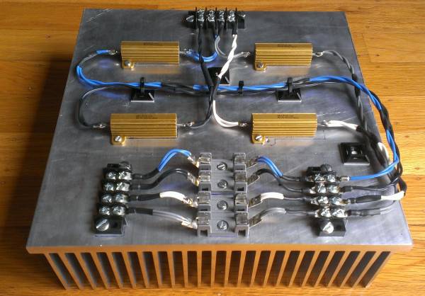
The resistors (MPC74s) are specified for 5W at 70°C ambient. But they do get very hot.
In our own example, they are over 140°C at the resistor body.
This is not surprising as a free standing MPC74 in 20°C ambient and 5W will get to 170°C in our measurement.
So the resistors will work properly under those conditions.
Because the top plate is not more than 40% perforated, it does receive quite a bit of that heat locally.
A wire grid as originally proposed will be better in that sense.
Of course the problem is solved by the much larger heat sinks in the CRegC.
If my memory is correct, Uwe likes the regulator more.
But I hope the feedback will come from the testers directly.
Patrick
Do you have a rough idea when the CRegC heatsink group buy will run? I think I'm going to build one CRC and wait for the new regulator sinks to finish my second build.
You get organised and tell us how many, then we need to find a production lot.
Finish date probably later summer to autumn. Factory is busy, so is Mark.
🙁
Patrick
Finish date probably later summer to autumn. Factory is busy, so is Mark.
🙁
Patrick
- Home
- Amplifiers
- Pass Labs
- F5X -- the EUVL Approach - The Build Thread