Hi permaneder,
they keep you busyyyy......😀😀
Hi generg,
nnnnnot really
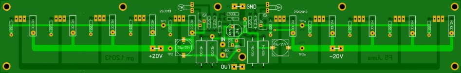
OK, now that I looked at the 2SK2013 datasheet I understand the choice of the source resistors better.
The gate−source has a voltage rating of 20V, so with a 20V PS you can keep the source resistors low, but with a 22V PS you can lower the voltage a little that the mosfets see if you use source resistors of 0.68 ohm
The gate−source has a voltage rating of 20V, so with a 20V PS you can keep the source resistors low, but with a 22V PS you can lower the voltage a little that the mosfets see if you use source resistors of 0.68 ohm
Hi,
Trying NOT to be a PIA, would/could you add a separate 0 volt point for the new added caps (thank you for that) to keep it away from the signal 0 volt point - current flow transients and all that 'stuff'
Trying NOT to be a PIA, would/could you add a separate 0 volt point for the new added caps (thank you for that) to keep it away from the signal 0 volt point - current flow transients and all that 'stuff'
Georg,
As an Alternative to using the 0 volt point on the pcb as the central Gnd point, the provision for operating this pcb with the central 0 volt point located at the power supply Regulator 0 volt point - an Option, if you will.
Also, if we were to continue this analogy, could you add a further provision to add a resistor between the signal input -ve wire and the pcb's gnd point. - it's a neater way of diong this if it's required - another Option
Sorry to add what might be seen as 'nit picking' things but options are so good to see on pcbs, especially if these don't produce problems.
Georg,
Also, if we were to continue this analogy, could you add a further provision to add a resistor between the signal input -ve wire and the pcb's gnd point. - it's a neater way of diong this if it's required - another Option
James,
It is my pleasure 😎. Even though I don't believe that it is necessary, I have isolated signal ground from 0V by RX.
Changes at the regulator boards are not longer possible without extra cost, as my boards producer's preparation work has been done already.
Attachments
It looks to be a completed design - I think that this pcb, and your supply brd will be around for quite awhile - many thanks.
I think that this pcb, and your supply brd will be around for quite awhile ...
especially if there will be ok 'alternative' mosfet replacements
James,
It is my pleasure 😎. Even though I don't believe that it is necessary, I have isolated signal ground from 0V by RX.
Changes at the regulator boards are not longer possible without extra cost, as my boards producer's preparation work has been done already.
Were you able to double up on the number of regulators per board?
Rush
Were you able to double up on the number of regulators per board?
Rush
Hi Rush,
First, the preparation work is already done by my boards supplier. Modifications now would cost additional EUR 45 at least.
Second, it would be necessary to considerably enlarge the boards’ sizes to guarantee a certain space between the MOSFETs to avoid thermal issues. More area = more money.
So, if you really want more current, I suggest to point-to-point wire the additional transistor(s). Be careful to solder the gate stopper resistors very close the transistors’ legs. There is no need to double the small capacitors and Zeners at the drains and sources yet.
Another solution might be the use of IRFP140/IRFP9140 (31A/21A)for example for more current.
Georg
Last edited:
Hi Rush,
First, the preparation work is already done by my boards supplier. Modifications now would cost additional EUR 45 at least.
Second, it would be necessary to considerably enlarge the boards’ sizes to guarantee a certain space between the MOSFETs to avoid thermal issues. More area = more money.
So, if you really want more current, I suggest to point-to-point wire the additional transistor(s). Be careful to solder the gate stopper resistors very close the transistors’ legs. There is no need to double the small capacitors and Zeners at the drains and sources yet.
Another solution might be the use of IRFP140/IRFP9140 (31A/21A)for example for more current.
Georg
Georg,
You have done a great job and more current is not what I am after when I asked if you had doubled up the number of regulators.
What I meant was, that with only a plus and minus on one board at $20 each (or whatever) we could get a lower cost per regulator if we made a larger board with 2 plus and 2 minus regulators on it so we could cut the board in half if we wanted to have two mono amps. The cost of one larger board with 4 regulators is less expensive than buying 2 boards with only 2 regulators on them.
Sorry for the confusion,
Rush
Rush,
Sorry for my misconception.
The costs for one dual mono set consisting of two +- regulator boards will be EUR 16 approximately. The quotation for the whole set on one board differs by less than EUR .30 (and I am not quite sure, whether my Czech suppliers really understood my question... 😕).
Expect a price in the range of EUR 22 for one stereo amp boards set (2 amp boards).
Georg
Last edited:
What's the effect of the regulators compared to a classic CLC power supply?
Example (simulation with PSUD2):
-With only a cap of 66mF you get about 600mV of ripple.
-With a CRC of 33mF-0.12ohm-33mF you get about 200mV of ripple.
-with a CLC of 33mF-5mH-33mF you get about 10mV of ripple, that's 20 times less compared to a CRC.
So where does the regulator fits in ?
Example (simulation with PSUD2):
-With only a cap of 66mF you get about 600mV of ripple.
-With a CRC of 33mF-0.12ohm-33mF you get about 200mV of ripple.
-with a CLC of 33mF-5mH-33mF you get about 10mV of ripple, that's 20 times less compared to a CRC.
So where does the regulator fits in ?
What's the effect of the regulators compared to a classic CLC power supply?
Example (simulation with PSUD2):
-With only a cap of 66mF you get about 600mV of ripple.
-With a CRC of 33mF-0.12ohm-33mF you get about 200mV of ripple.
-with a CLC of 33mF-5mH-33mF you get about 10mV of ripple, that's 20 times less compared to a CRC.
So where does the regulator fits in ?
I do not simulate – too old and dumb…🙁
A few years ago I measured the regugulated supplies with an oscilloscope and a Fluke 189 multimeter (combined DC and effective AC measurement). The load capacitance was 22mF, the buffer capacitance at the regulated outputs a second 22mF cap. Vout was 24V @ 2A load current as far as I remember.
There was no ripple visible.
The regulators are death quiet and very dynamic. I prefer them over any passive supplies including CLC.
What transformer should I buy for this amp and regulator?
300VA 2*22V per channel
Is 2*22 VAC per channel not too much ? Is 2x19 VAC not better ?
In my F5 I have a 500VA 2x18 transformer that gives me rails of 23vdc after the CLC.
If the regulators drop the voltage 4v then 2x19vac looks perfect.
In my F5 I have a 500VA 2x18 transformer that gives me rails of 23vdc after the CLC.
If the regulators drop the voltage 4v then 2x19vac looks perfect.
Is 2*22 VAC per channel not too much ? Is 2x19 VAC not better ?
In my F5 I have a 500VA 2x18 transformer that gives me rails of 23vdc after the CLC.
If the regulators drop the voltage 4v then 2x19vac looks perfect.
You'll need at least 8V over the wanted regulated Vout @ full load current for a stiff supply. Even more, if your transformers are not proper dimensioned. The bigger the iron, the better.
Last edited:
- Status
- Not open for further replies.
- Home
- Amplifiers
- Pass Labs
- F5 with 2SK2013/2SJ313