I think in class A the peak current is about half of bias current.
For the F5? The class A envelope of a push-pull amp is slightly less than double (not half) the bias current. So, if you run the amp at 500mA, you have around 1A of current available before the amp leaves class A.
Actually the peak output for these will be in excess of twice the bias,
depending on the amount of Source resistance degenerating the gain.
For purely square law devices operated push-pull (no resistance in series
with Source pin) the theoretical number is 4 times bias current. With large
values of Source resistance, it declines toward 2 times.
This being an imperfect world, you usually see un-degenerated Fets doing
about 3 times bias.
Mr Pass,
Thanks for explaining that - I got it the other way around. So if I am run I g 1.5amp bias in my amp, it can push about 3amps to as much as 4.5amps in class A through the speaker? Well that's good to know. If I am running 25v rails isthe max power about same as regular F5 at 25w? Do you see any issue with me changing the gain to 20dB?
Thanks for explaining that - I got it the other way around. So if I am run I g 1.5amp bias in my amp, it can push about 3amps to as much as 4.5amps in class A through the speaker? Well that's good to know. If I am running 25v rails isthe max power about same as regular F5 at 25w? Do you see any issue with me changing the gain to 20dB?
I just installed real 5k NTC's thermally coupled to the MOSFETs. It's tracking the bias much better now. The 5k pot is still very touchy. I will measure the value and get a 500R in its place in series with a resistor to get better resolution of bias setting and control.
Thanks a lot so far! So better not to go below 15 V rails for 8 Ohm speakers in order to get the max out of the one pair of fets. If I went that route, would I have to change any resistor within the first stage?
P = IV = I²R = V²/R, for unchanging DC voltage and current.I think in class A the peak current is about half of bias current. If I did this right it means you need 0.45amps for 5w into 8ohms. These are rated at 1A and should operate probably no more than 500mA ea to be safe. So having two should give you room for peak 500mA into speakers. Rail voltage needs to be maintained so that there is enough room for 6.3v rms. Maybe +/-12v could work?
For AC waveforms this becomes:
P = IrmsVrms = Irms²R = Vrms²/R
and for a sinewave it can also be expressed using peak value of the waveform:
P = IpkVpk/2 = Ipk²R/2 = Vpk²/R/2
using this last P=Ipk²R
we see that 0.45Apk will allow 0.81W to be dissipated in an 8r0 dummy test load.
If you want 5W then rearrange the equation to become Ipk = sqrt(2P/R) =1.18Apk into 8r0 needing a drive voltage of 8.94Vpk
Last edited:
P = IV = I²R = V²/R, for unchanging DC voltage and current.
For AC waveforms this becomes:
P = IrmsVrms = Irms²R = Vrms²/R
and for a sinewave it can also be expressed using peak value of the waveform:
P = IpkVpk/2 = Ipk²R/2 = Vpk²/R/2
using this last P=Ipk²R
we see that 0.45Apk will allow 0.81W to be dissipated in an 8r0 dummy test load.
If you want 5W then rearrange the equation to become Ipk = sqrt(2P/R) =1.18Apk into 8r0 needing a drive voltage of 8.94Vpk
I don't think this is consistent with what Mr. Pass said:
Actually the peak output for these will be in excess of twice the bias,
depending on the amount of Source resistance degenerating the gain.
For purely square law devices operated push-pull (no resistance in series
with Source pin) the theoretical number is 4 times bias current. With large
values of Source resistance, it declines toward 2 times.
This being an imperfect world, you usually see un-degenerated Fets doing
about 3 times bias.
using this last P=Ipk²R
we see that 0.45Apk will allow 0.81W to be dissipated in an 8r0 dummy test load.
P=0.45A squared x 8ohms = 1.62w
There's a typo in line 6
It should read:
"using this last P=Ipk²R/2"
copied from line 5
as far as I can see all the rest is correct.
It should read:
"using this last P=Ipk²R/2"
copied from line 5
as far as I can see all the rest is correct.
I want to add the regulated PSU that Juma designed:

It's a very simple circult and I am hoping that it helps reduce the hum I am getting from rail ripples under load. Can someone explain to me how this circuit works and where the 20V reference is coming from? If I want to run it at say, 22V what do I need to adjust?
It's a very simple circult and I am hoping that it helps reduce the hum I am getting from rail ripples under load. Can someone explain to me how this circuit works and where the 20V reference is coming from? If I want to run it at say, 22V what do I need to adjust?
It's a simple C-Multiplier circuit, not a regulator (with an R-C filter on the output cap) - use lower drop out voltage power fets or transistor - output capacitors directly effect the sound of the amp
There's a "mkII" version of Juma's C-Multi that uses 4 NMosfet IRFP044 (and according to the designer, performs better)
So if I am run I g 1.5amp bias in my amp, it can push about 3amps to as much as 4.5amps in class A through the speaker?
If I am running 25v rails is the max power about same as regular F5 at 25w?
Do you see any issue with me changing the gain to 20dB?
1) With a .47 ohm Source resistor, probably about 3.5A pk
2) Yes, 25W
3) 6 dB more gain = twice as much distortion, half the damping factor.
Capacitance Multiplier
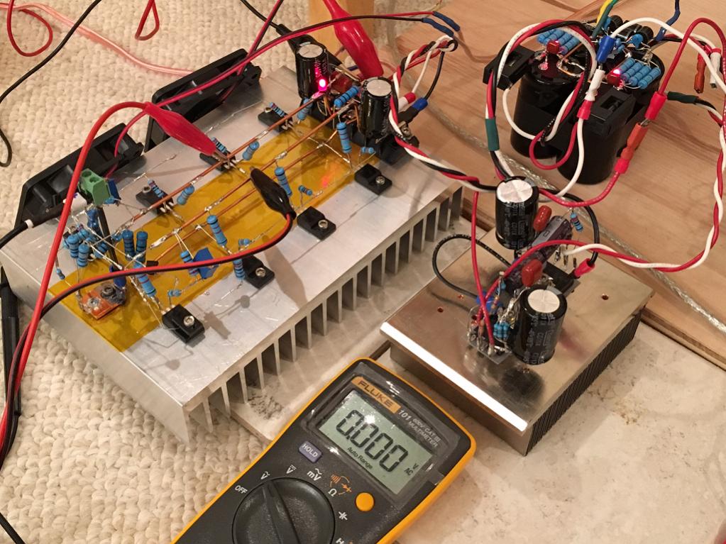
I implemented Juma's capacitance multiplier on a separate heatsink. I have to say that it was simple and I works very well. I am getting 22v rails no load and 19.5v rails under full load with 1.5amps bias current. Ripple measured with AC volts on Fluke is less than 1mV as shown below. Quite an amazing performance from the previous 40mV ripple coming from the CRC filter.
The circuit is so simple, I easily did it with P2P right on top of the IRFP240/9240's.
Attachments

I think the cap multiplier is a real gem - sharing. My experience over on SS forum:
http://www.diyaudio.com/forums/solid-state/297921-jumas-easy-peasy-capacitance-multiplier.html
http://www.diyaudio.com/forums/solid-state/297921-jumas-easy-peasy-capacitance-multiplier.html
There's a "mkII" version of Juma's C-Multi that uses 4 NMosfet IRFP044 (and according to the designer, performs better)
Would that be this one?
Attachments
There's a "mkII" version of Juma's C-Multi that uses 4 NMosfet IRFP044 (and according to the designer, performs better)
Did he happen to say why that would be?
Would be that you now have better matched ripple reduction and rail values
with just N-channel parts since the N and P parts have different Vgs and
transconductance?
with just N-channel parts since the N and P parts have different Vgs and
transconductance?
That is a good argument for the topology, but doesn't give insights as to
why the IRFP044 would be the transistor of choice.
why the IRFP044 would be the transistor of choice.
- Status
- Not open for further replies.
- Home
- Amplifiers
- Pass Labs
- F5 with 2SK2013/2SJ313