what load ?
amp or speakers ?
it's classA
load is not changing, is it ?
amp
very practical in testing phase when you need to move and change things.
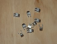
For your next Bürklin order :
Riacon single-wire screw terminals, 16A.
09H5920 (9x9mm) or 09H594 (5x5mm)
Section H of the paper catalogue, page ~930
(what a pretty avatar you have)
Thanks, that looks very promising.For your next Bürklin order :
Riacon single-wire screw terminals, 16A.
09H5920 (9x9mm) or 09H594 (5x5mm)
Section H of the paper catalogue, page ~930
(what a pretty avatar you have)
Part of my other DIY adventure: RC boat modelling 🙂
6.3mm spades are long-time reliable connectors. I do use them in my amp builds since more than 30 years without any failure.
There must be good reason, why they are applied in extremely demanding automotive applications, for example.
...
I overlooked this post but I have to get back to it since the claims it contains are false and dangerous.
I'm in electronics for more than 30 years too. I used to repair very expensive equipment - 10KW SW radio transmitters and injection molding machines, to name some.
Many failures led back to removable connections gone bad.
Simply put, it's inferior way to make the electro-mechanical connection. It's just a way for manufacturing company to make more money during the after-sale period through increased maintenance demands.
With time passing that kind of connection becomes loose, oxidation builds up, the resistance of the joint increases (and it's not small to begin with), where high voltage is present arcing quickens the deterioration.
Of course, those thingies are convenient but there is a price to be paid for that.
So stay away from that crap or accept inferior results and failures waiting to happen.
not sure they are that bad
but there are so many brands, types, and slightly different sizes
it is almost impossible to get the right ones that fits properly
and weird listing by supplier is not making it any easier
I gave up
instead it will be heavy duty 15A(amp) print connectors with 3mm mounting screw 😀
but there are so many brands, types, and slightly different sizes
it is almost impossible to get the right ones that fits properly
and weird listing by supplier is not making it any easier
I gave up
instead it will be heavy duty 15A(amp) print connectors with 3mm mounting screw 😀
I 'm aware that it's easier to learn how to use the screwdriver than the soldering iron, but it's worth the effort...
some wire connections are great for soldering, and some not
actually, before this I have always soldered all my connections
I only hope these are a bit better that the commonly used crappy print connectors
but ofcourse these are only intended for power supply connections
actually, before this I have always soldered all my connections
I only hope these are a bit better that the commonly used crappy print connectors
but ofcourse these are only intended for power supply connections
Attachments
I am sure they are not that bad.not sure they are that bad.......D
A gas tight metal to metal joint is very good in the very long term.
Single K2013 & J313 output pair
Anybody tried a single pair without source degeneration resistor nor the ntc at 600mA zero tempco point and dual 12V? Sounds ok, bad or fire maker? Plan to use on TL FE206.
Anybody tried a single pair without source degeneration resistor nor the ntc at 600mA zero tempco point and dual 12V? Sounds ok, bad or fire maker? Plan to use on TL FE206.
some wire connections are great for soldering, and some not
actually, before this I have always soldered all my connections
I only hope these are a bit better that the commonly used crappy print connectors
but ofcourse these are only intended for power supply connections
I've used these Keystone connectors for years. They make a wide variety,
up to 30A rating. It makes a very solid connection right to the pcb.
Hi Juma,
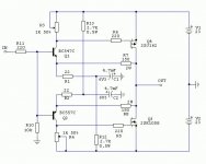
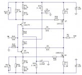
I attached 3 of Yours schematics. I want to build headphone amp based on 2SJ313/2SK2013 @ 200mA +-15V based on schematics 3. Because of unobtanium JFETs, it will be very nice if I can use BJT front end, just like on schematics 1 and 2, but that schematics are for different output devices.
So schematics is topologically identical as schematics 3, only Q5, Q6 are BC550/560 , and wanted bias current of output FETS (2SJ313/2SK2013) is 200 mA.
Doable?
Many thanks in advance.
PS
Link to PCB work in progress
Attachments
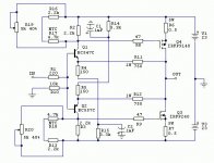
Sure, see attachment....Doable? ...
This way we avoid JFETs and big caps in the feedback loop.
Q5-8 form CCSs (about 1mA) that supply the input buffer (Q1,2) which polarizes Q3,4 (about 3mA).
Output stage doesn't need thermal compensation (due to relatively high value of R16,18). Just take care to provide enough heatsinking for the output MOSFETs (each dissipates about 15V x 0.2A = 3W ) so that temperature on them doesn't rise to more than 15-20 degrees Cels. above ambient.
You can use bc550c/560c or similar on all positions.
Bias setting procedure (P1,2) is the same as for F5 - set the voltage drop over R16,18 to 660mV for Id=0.2A.
The value of freq. compensation caps (C1,2) can be adjusted for best square wave response and stability. Power rail bypass caps (100-1000 uF) can be added if they don't influence stability (that will depend on your build, PSU and the parts used).
Attachments
Many thanks Juma.
Plan is to use this heatsink:
SK 129 50,8, Extruded heatsinks for PCB mounting, Heatsinks f.cool, Fischer Elektronik
Plan is to use this heatsink:
SK 129 50,8, Extruded heatsinks for PCB mounting, Heatsinks f.cool, Fischer Elektronik
IME, Fischer K/W numbers are not to be trusted - I'd rather use SK453 or SK434
Or, you can lower the current through the output stage ...
P.S.
Vent-holes below and above the heatsinks are mandatory.
Or, you can lower the current through the output stage ...
P.S.
Vent-holes below and above the heatsinks are mandatory.
Hi Juma, to further expand the number of (good) headamp schematics that are coming out in those days, what about a Cubie2 with 2SJ313/2SK2013@100.mA?
Thanks
Guido
Thanks
Guido
It will work great too - just take care about higher Vgs needed for k2013/j313 and don't forget to add source resistors for them (3R3-4R7) to provide sufficient thermal stability....what about a Cubie2 with 2SJ313/2SK2013@100.mA?...
hi juma,
how about using hitachi k135 j50 mosfets? any modification needed?
and are there any chance to make them turbo? (f5 turbo latfet)
thanks.
Peter
how about using hitachi k135 j50 mosfets? any modification needed?
and are there any chance to make them turbo? (f5 turbo latfet)
thanks.
Peter
Sure. The end result will be this:
http://www.diyaudio.com/forums/pass...riant-gr-grade-jfets-latfets.html#post3980775
k135/j50 = k1058/j162
Yes, you can turbo it the usual way:
- raise the PS voltage
- cascode the JFETs
- put more paralleled LATFETs in the output stage
http://www.diyaudio.com/forums/pass...riant-gr-grade-jfets-latfets.html#post3980775
k135/j50 = k1058/j162
Yes, you can turbo it the usual way:
- raise the PS voltage
- cascode the JFETs
- put more paralleled LATFETs in the output stage
Last edited:
- Status
- Not open for further replies.
- Home
- Amplifiers
- Pass Labs
- F5 with 2SK2013/2SJ313