I'm building my first amp and, as the title obviously indicates, I'm going to try an F5. I'm not going to use any pre-made pcb's, and I'm just learning electronics, so I am looking to have someone fact check this layout. Yes, it's Mr. Pass' exact layout, but it's hard enough for me to reverse engineer this with my skill so it makes it a little easier for me to visualize. Anyway, enough excuses, please review this and let me know if I connected everything like my picture, would it be ok?
Attachments
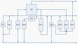
The connections drawn seems correct. But only the positive part is drawn.
You may have good reasons not to get a PCB from e.g. Peter Daniel. I will however strongly suggest you get PCBs for this project. See http://www.diyaudio.com/forums/showthread.php?t=140306 for details. This makes errors much less likely.
Regds
R-K
You may have good reasons not to get a PCB from e.g. Peter Daniel. I will however strongly suggest you get PCBs for this project. See http://www.diyaudio.com/forums/showthread.php?t=140306 for details. This makes errors much less likely.
Regds
R-K
Thank you for your response. Yes, I figured I would try to make sure I understood V+ for one channel and if I could at least get that right, I would finish out the whole channel. I'm also going to try and separate the power supply.
This is all a big learning experience as much as it is building a cool amp that I can use when I'm done. I'm really a learn by doing kind of guy. I can read something over and over, but until I blow it up, er, I mean, get it to work, it doesn't always sink in. I am also looking at doing something eclectic with the "case" and "pcb" so pre-fabbed pcb's don't fit the bill.
This is all a big learning experience as much as it is building a cool amp that I can use when I'm done. I'm really a learn by doing kind of guy. I can read something over and over, but until I blow it up, er, I mean, get it to work, it doesn't always sink in. I am also looking at doing something eclectic with the "case" and "pcb" so pre-fabbed pcb's don't fit the bill.
You'll learn much more doing it yourself. PCB's are nice of course, but it ain't the same. More power to you!
I have both the PeteDaniel boards, and Cvillers
Both very nice
But I still like to play with this
Just be aware of errors
They seem to happen every time I make changes😱
Would be fun to try and make double sided boards, but Im certain I would choose hardwire on thin Pertinax plate
But playing with the board layout still seems to give me some idea about how to hardwire it
Attachments
Last edited:
Thank you all for the information and kind words. I'll be sure to update as I progress with the project.
full channel
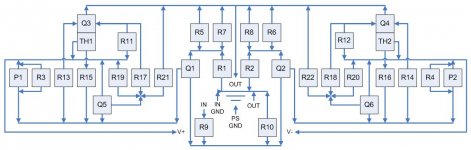
Well, here goes the full channel. I don't think I screwed anything up moving it all around, but there's always a chance. Would there be a problem if I actually terminated all the connectors as diagrammed in the middle there? I was trying to sift through the thousands of posts for what should and shouldn't be near each other, but most everything that came up was PS related.
I was even thinking of pulling out all of the center R1-R2, R5-R10, Q1-Q2 onto another board entirely. What would be the pros & cons of that?
Attachments
Hi
I think Nelson has stated that layout doesnt make significant difference
I think it was also stated that its important not to have input signal close to supply rails
And THAT you seem to have
But your layout looks good
I may try to do layout that way
I think Nelson has stated that layout doesnt make significant difference
I think it was also stated that its important not to have input signal close to supply rails
And THAT you seem to have
But your layout looks good
I may try to do layout that way
Last edited:
All right, I was mostly just looking to make a tight, simplified connection area. As you can see the supply lines are actually just wrapped around the ends. When I actually wire them, since I'm going to try a hybrid* pcb/p2p, I was going to go from underneath R11/R12 and just pop them up next to R9/R10. I was worried about them being too far apart as I thought I had read that they should be twisted around each other to help reduce...inductance(??). I guess I'll pop them up around P1/P2 instead then if they should be farther away from the input.
*I'm pretty much a function over form kind of guy, but I'm also a little neurotic about balance and symmetry. (as if you didn't get a feel for that from my drawings) So I like stuff to at least look somewhat clean and organized. When I was talking to the friend that introduced me to this whole diy amp/speaker stuff, we were talking about his tube amps and how we liked the more old school/steampunk look of them. Then we started talking about crazy ways to display them and came up with some kooky stuff. Due to the heatsink weights and temperatures I'm not sure how well it will all work, but I'm thinking of doing some type of lexan with the schematic etched/printed/drawn/something onto it with the parts attached much like a normal pcb. There would be some free wire for the bus' and connections. The idea would be to try and have it hung on the wall with cables just kind of draping down and stuff. My dormant artist is awakening, and since it's been repressed for so long, it's causing me to think of some stuff in a really weird way without a lot of consideration to much besides form (function!, no...form!, no...function! shut up, or someone will see me talking to myself!). I honestly haven't even put any design into WAF and just hope she goes with it.
*I'm pretty much a function over form kind of guy, but I'm also a little neurotic about balance and symmetry. (as if you didn't get a feel for that from my drawings) So I like stuff to at least look somewhat clean and organized. When I was talking to the friend that introduced me to this whole diy amp/speaker stuff, we were talking about his tube amps and how we liked the more old school/steampunk look of them. Then we started talking about crazy ways to display them and came up with some kooky stuff. Due to the heatsink weights and temperatures I'm not sure how well it will all work, but I'm thinking of doing some type of lexan with the schematic etched/printed/drawn/something onto it with the parts attached much like a normal pcb. There would be some free wire for the bus' and connections. The idea would be to try and have it hung on the wall with cables just kind of draping down and stuff. My dormant artist is awakening, and since it's been repressed for so long, it's causing me to think of some stuff in a really weird way without a lot of consideration to much besides form (function!, no...form!, no...function! shut up, or someone will see me talking to myself!). I honestly haven't even put any design into WAF and just hope she goes with it.
- Status
- Not open for further replies.
- Home
- Amplifiers
- Pass Labs
- F5 wiring