Hi,
I have already built the F5 as per original schematics. I like the sweet sound of the amp for moderate listening levels but I would like to get more power and more voltage gain while keeping it simple (like the F5).
I saw some posts on making the F5 balanced X amp but it is not my goal.
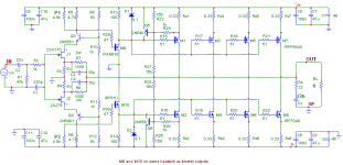
This is the schematics I came up with to get about 80-90W rms (8 ohms).
The heatsink size would allow about 10Wrms (8 ohms) class A and the rest of power in class AB.
It has a cascode input to handle higher voltage rails.
It has a mosfet driver stage to increase the drive current (35ma) for the 4 pairs of mosfet outputs. This vertical mosfet driver also allows to get more gain from input stage (higher drain resistance) at the same time because of the high threshold voltage compared to lateral mosfet or BJT...
To keep enough feedback factor while increasing the voltage gain to about 26db, the open loop gain is increased by paralleling output mosfet and modifying the input stage bias (3 ma).
Can you comment if this design has some potential...🙂
Thanks
Fab
I have already built the F5 as per original schematics. I like the sweet sound of the amp for moderate listening levels but I would like to get more power and more voltage gain while keeping it simple (like the F5).
I saw some posts on making the F5 balanced X amp but it is not my goal.
This is the schematics I came up with to get about 80-90W rms (8 ohms).
The heatsink size would allow about 10Wrms (8 ohms) class A and the rest of power in class AB.
It has a cascode input to handle higher voltage rails.
It has a mosfet driver stage to increase the drive current (35ma) for the 4 pairs of mosfet outputs. This vertical mosfet driver also allows to get more gain from input stage (higher drain resistance) at the same time because of the high threshold voltage compared to lateral mosfet or BJT...
To keep enough feedback factor while increasing the voltage gain to about 26db, the open loop gain is increased by paralleling output mosfet and modifying the input stage bias (3 ma).
Can you comment if this design has some potential...🙂
Thanks
Fab
Attachments
seems like a possible way to go.
I'd not want to use any bipolar transistors myself...
Of course it is no longer an F5 at this point.
Where are you picking up the extra gain... maybe you can post the gains per stage (OL)? Is it all in the cascode?
_-_-bear
I'd not want to use any bipolar transistors myself...
Of course it is no longer an F5 at this point.
Where are you picking up the extra gain... maybe you can post the gains per stage (OL)? Is it all in the cascode?
_-_-bear
Open loop gain
Hi Bear,
Most of the extra gain comes from the added parallel mosfets where the mosfet in common source configuration has a gain of about RL * gm where RL = 8 and gm = [5 -7] for IRFP240/9240. Thus each added pair adds about 5 of gain or so. Thus if 3 pairs gives about 15 of gain than it corresponds to the loss of feedback factor due to the closed loop gain increase from original F5 design...
The cascode should not add much gain but the Rload of the jfet input is increased by reducing the Id and having the VGSoff the IRF610(9610) requiring more voltage drop across Rload.
Yes it is no longer an F5 but can it provide good sound (at higher audio level)even if different?
I wonder if only 3 pairs with higher bias would provide better sound than with 4 pairs...
Also, regarding the cascode with bipolar, is my "floating" reference a good idea?
Thanks
Fab
seems like a possible way to go.
I'd not want to use any bipolar transistors myself...
Of course it is no longer an F5 at this point.
Where are you picking up the extra gain... maybe you can post the gains per stage (OL)? Is it all in the cascode?
_-_-bear
Hi Bear,
Most of the extra gain comes from the added parallel mosfets where the mosfet in common source configuration has a gain of about RL * gm where RL = 8 and gm = [5 -7] for IRFP240/9240. Thus each added pair adds about 5 of gain or so. Thus if 3 pairs gives about 15 of gain than it corresponds to the loss of feedback factor due to the closed loop gain increase from original F5 design...
The cascode should not add much gain but the Rload of the jfet input is increased by reducing the Id and having the VGSoff the IRF610(9610) requiring more voltage drop across Rload.
Yes it is no longer an F5 but can it provide good sound (at higher audio level)even if different?
I wonder if only 3 pairs with higher bias would provide better sound than with 4 pairs...
Also, regarding the cascode with bipolar, is my "floating" reference a good idea?
Thanks
Fab
Last edited:
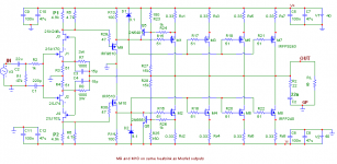
Remove bipolar...
Like this cascode:
seems like a possible way to go.
I'd not want to use any bipolar transistors myself...
....
_-_-bear
Like this cascode:
Attachments
The placement of the limiters will probably blow out the
drivers. Probably better to just take the limiters out.
😎
drivers. Probably better to just take the limiters out.
😎
Limiters
I do not understand why. It takes quite a large amount of load current to activate them. My simulator does not show clipping until less than 1 ohm load. Unless you mean that I should limit more the current...😕
thanks
Fab
The placement of the limiters will probably blow out the
drivers. Probably better to just take the limiters out.
😎
I do not understand why. It takes quite a large amount of load current to activate them. My simulator does not show clipping until less than 1 ohm load. Unless you mean that I should limit more the current...😕
thanks
Fab
1 ohm Hmmmmm.... i can test for you ..... 😀
Of course, this is a simulator...😉
I do not understand why. It takes quite a large amount of load current to activate them. My simulator does not show clipping until less than 1 ohm load. Unless you mean that I should limit more the current...
M9 and M10 are Mosfet followers. They can deliver a lot
of current, and you are more or less shorting their Sources
to the rails.
Current will flow, sparks will fly.
😎
Limiters...
I think I understand now...🙄
Do you mean that if the current limiters are activated one day than I could blow off the M9 and M10
Thanks
Fab
M9 and M10 are Mosfet followers. They can deliver a lot
of current, and you are more or less shorting their Sources
to the rails.
Current will flow, sparks will fly.
😎
I think I understand now...🙄
Do you mean that if the current limiters are activated one day than I could blow off the M9 and M10
Thanks
Fab
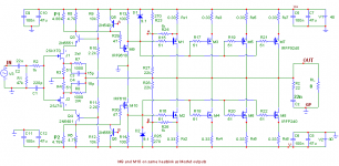
I have placed the limiter transistors (Q5 and Q6) in parallel with the input jfet loads to avoid shorting the M9 amd M10. However, the more I think about it, I am not sure if this amp really needs such a limiter since the open loop gain of the amp (thus the closed loop gain) tends to reduce considerably upon a big reduction of load impedance...
Attachments
Last edited:
Hi fab,
Yeah, I am not looking at things and seeing what is in front of me that is if I had a clue. The outputs have gain... ya.
Yes I would personally prefer to have a jfet as the cascode. Will it make any difference in the sound? I dunno.
Will this sound like an F5?
Hard to say exactly what an F5 sounds like.
It seems to me that the design is somewhat variable depending on the specifics of the implementation...
I'd say it is worth trying to build.
I'd go for more Marshferts in the output than less, but that depends on the current available from the drivers and their ability to drive the capacitance of those gates. Or at least this is the common wisdom, I am told.
I am not a fan of limiters - I say smoke the sucker if that's what's required to get the best sound... of course it is a good thing to have an amp that is stable and does not let the magic smoke out of the parts.
Do you need that cap at the input? Mmmm... maybe unless you have supreme confidence in ur signal path being DC free. So, maybe two inputs, one "chicken" and one "daring"?? 🙂
....
Current will flow, sparks will fly.
decent Haiku ;
again .
Hi fab,
....
Yes I would personally prefer to have a jfet as the cascode. Will it make any difference in the sound? I dunno.
Will this sound like an F5?
Hard to say exactly what an F5 sounds like.
....
I'd say it is worth trying to build.
I'd go for more Marshferts in the output than less, but that depends on the current available from the drivers and their ability to drive the capacitance of those gates. Or at least this is the common wisdom, I am told.
....
Do you need that cap at the input? Mmmm... maybe unless you have supreme confidence in ur signal path being DC free. So, maybe two inputs, one "chicken" and one "daring"?? 🙂
Hi Bear,
The jfet cascode does not allow to "spent" a large voltage of the supply rail... I may have to stick to the bjt cascode with 40vdc supply...
I would expect more comments before trying to build it .... since it does not seem to get a lot of attention so far...🙄
This is one of the questions I tried to raise in my first post: Is 35ma enough to drive 4 mosfet pairs of IRFP240/9240 for about 80W (8 ohms) or 160W (4 ohms)?😕
For the input cap, I do not trust the sources of the amp. The amp can be used in a lot of setups also from other peoples for audio test purpose..
Thanks
Fab
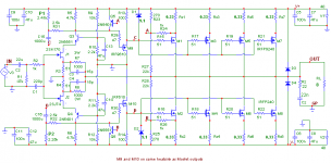
Larger Open loop gain with bootstrap...
This one with a bootstrap (C15/C16, R31/R32) provides about 6db more open loop gain according to my simulator.
Is there a schematics posted that has better potential than the others?
What can I do to improve it?
Thanks
Fab
This one with a bootstrap (C15/C16, R31/R32) provides about 6db more open loop gain according to my simulator.
Is there a schematics posted that has better potential than the others?
What can I do to improve it?
Thanks
Fab
Attachments
.......
This is one of the questions I tried to raise in my first post: Is 35ma enough to drive 4 mosfet pairs of IRFP240/9240 for about 80W (8 ohms) or 160W (4 ohms)?😕
......
Aleph 5 - ring a bell ?
count driven gates
Given that you have a middle stage, do you still need to swing rail-to-rail with the first stage? Can you make up the gain (what would it be, like 6dB?) in the second?
Given that you have a middle stage, do you still need to swing rail-to-rail with the first stage? Can you make up the gain (what would it be, like 6dB?) in the second?
But the middle stage is a follower. From what I know, only inverted stage allows gain. Since the first and output stages are inverting I can not invert in the middle stage. The first stage load voltage determines the bias for the output...
Thanks
Fab
I think I would insert a resistor from driver's drains to ground.
Hi
But the driver's drain is already directly connected to ground. Do you mean to connect a resistor instead of a direct connection to ground?
Thanks
Fab
- Status
- Not open for further replies.
- Home
- Amplifiers
- Pass Labs
- F5 type amp but with higher power