I am working on a pair of F5T V3 mono blocks. The toroidal's secondary voltage rated 40v/1000VA, the +/- rail voltage going to be 56-58v loaded.
What particular value of the component needed to be change to accommodate the higher rail voltage? NP mentioned that the Jfets see about 1/3 of the rail voltage from the voltage divider R25 and R27.
If I change R25 to 12.8k, R27 same as the schematic value 4.75k, assume the rail at 57v then the Jfets will see 15.43v.
R5, R6 1k resistor for the BJT 2SC4793 and 2SA1837 but these two items just can't get them any more. If those two cascode BJTs substitute to MJE15034 and MJE15035, R5 and R6 can be the same value 1k with 57v rail? And the above BJTs are suitable candidate?
The feedback resistors R7 through R10 value would be adequate?
I do try to search but just can't find the match or I just missed. The moderators feel free to move if needed.
Attachments
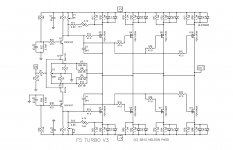
loaded rectifier with filter will result in Vdc closer to Vac x 1.25 ;
Vac x 1.41 is reserved for unloaded/light loaded rec+filt.
set appropriate resistors that bases of cascode BJTs are at , say , + and - 12V , so JFets would see 11V35 ..... you can go volt or so even lower
MJE are good
R5, R6 - do not change them , rails voltage is not having any relation with tjeir value
leave feedback resistors as they are , investigate later are you satisfied with gain of circuit , make changes only if and when needed
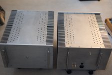
F5Tv3 Finished
I finally finished these big monster amps. Thank you Tea-Bag to the match mosfets, Spencer to the match jfets, Zen Mod's advised and Dazed2's slow charge schematic.
The aluminum plates cut to size from local shop. Heat sinks ordered from Heatsink USA. Drawer pulls from home center. Fasteners and feet set from Mcmaster Carr. The chassis is the most time consuming task. Tapping, drilling and jig fabricating took more then 3 weekend of work to finish.
The bias set to 320mV, DC offset around 1-2mV. Temperature about 21 deg C at the sinks. The P3 trimmer will try it later.
It's a big project that require a lot of patience and elbow grease to accomplish. I think I won't build any big wattage class a amp in the near future because it just too heavy to moving around.
Attachments

Really nice work syyma. I know what you mean about drilling and tapping taking so much time. I find keeping hole center spacing and matching to object that will be bolted together a real challenge.

Fugly!

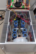
though , keep an eye on inner temperature ; you don't want those caps burned in year or so
if needed , open more slots both on bottom and top
there are few simple solutions , not needing (full) dismantle of bottom plate
though , keep an eye on inner temperature ; you don't want those caps burned in year or so
if needed , open more slots both on bottom and top
there are few simple solutions , not needing (full) dismantle of bottom plate
6L6,
Haven't decided yet.
Zen Mod,
I will put a temp gauge to monitoring the inside.
Your advice are more then welcome.
Haven't decided yet.
Zen Mod,
I will put a temp gauge to monitoring the inside.
Your advice are more then welcome.
Truly impressive case work. Great job on keeping those holes aligned in the top plate.
If you want to add more cooling for the internal components, you could increase the diameter of the holes in the bottom plate to 5/16 in. or so. That should let some convection air currents flow between the heatsinks and the bank of $$ capacitors. I wouldn't touch the top plate, it looks so nice, and should be good for air flow as is.
If you want to add more cooling for the internal components, you could increase the diameter of the holes in the bottom plate to 5/16 in. or so. That should let some convection air currents flow between the heatsinks and the bank of $$ capacitors. I wouldn't touch the top plate, it looks so nice, and should be good for air flow as is.
Bottom plate
TungstenAudio,
The bottom plate already have a lot of 3/8" holes, there is a 5/16" gap between the bottom end of the capacitor and the bottom plate.
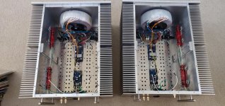
I use grid paper as a holes template to put the punch marks. Get pilot holes at one plate then set as a drill template on top of other plate to save time and better consistency.
TungstenAudio,
The bottom plate already have a lot of 3/8" holes, there is a 5/16" gap between the bottom end of the capacitor and the bottom plate.
I use grid paper as a holes template to put the punch marks. Get pilot holes at one plate then set as a drill template on top of other plate to save time and better consistency.
Attachments
At high rails you would want to put some resistance in series with the Drains
of Q1 and Q2 for potential oscillation issues. 100 ohms ought to do it.
of Q1 and Q2 for potential oscillation issues. 100 ohms ought to do it.
Papa,
Your advices are valuable and taken.
So far the amps are co-operated, no sign of oscillation. The rail voltage around +/-52-54v, all depends on the power company, at some point the line voltage as high as 125v.
Your advices are valuable and taken.
So far the amps are co-operated, no sign of oscillation. The rail voltage around +/-52-54v, all depends on the power company, at some point the line voltage as high as 125v.
At high rails you would want to put some resistance in series with the Drains
of Q1 and Q2 for potential oscillation issues. 100 ohms ought to do it.
Are 40V rails considered "high"?
Congratulations! That must have been a huge amount of work, putting those chassis together with all those holes to drill and/or tap. Your operating point is .64A/output at 57volts? Looks like about 36w/mosfet.
To make them easier to move you could put the power supplies in separate boxes. But then you would have 4 boxes.
That’s how I built mine. I am running at 47v .55amp/output. I have the last C of the CLC filter in the amp box and the rest of the supply in it’s own box.
I have Jensen input transformers on the front end of my F5v3s so I can use them with balanced sources. I like them a lot. I think you will be very pleased with the sound!
Are 40V rails considered "high"?
The issue is stability with cascoding. Cascodes are often employed when
the rail voltages are high.
Hi, I have a 2000VA 2x41Vac toroidal transformer and I would like to build 2 monoblocks Pass F5 Turbo V3. Please help me with what mods I should do for power supply and/or amplifier section. Thanks
Thanks, so I can use 2x41Vac but I have to be careful at bridge rectifiers an caps bank voltage ...something like greater than 80V.

- Home
- Amplifiers
- Pass Labs
- F5 Turbo V3 +/-58v rail voltage questions