Ok, I'll post the proposed final designs here because at some point corrections were made. Melon Head, would be very grateful if you'd look them over, then we can send them off to the PCB fab.
Attachments
Ok, I'll post the proposed final designs here because at some point corrections were made. Melon Head, would be very grateful if you'd look them over, then we can send them off to the PCB fab.
First off, I was just referring to the template for the hole positions on the heatsing
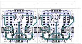
This is exactly the way I like it. I have not checked the fine details but generally speaking, I like separating the front end pcb from the output, that way if people say "I want more mosfets at the output" you don't have to redesign a whole new pcb, you just design bigger output boards.
Ideally the front end should contain everything so that someone can go absolutely nuts with it.
First impression is very good.
I will check it against circuit diagram.
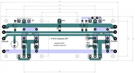
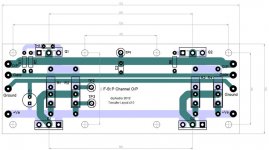
We don't even have to design bigger output boards. Two output boards will bolt onto each heatsink on our big chassis and you can just daisy chain two boards together on each side to make a monster monoblock. If you want an n and p on each side for 2 channel that will bolt in place too.
The medium chassis only accommodates one board per side. Because it doesn't make sense to make a two channel F-5t in the medium chassis.
But again, you can put a "p" on one side and and "n" on the other to make a monoblock F-5t
Check the Universal Mounting specification in the Store here:
http://www.diyaudio.com/store/boards.html
And you'll see that the diodes just bolt on too..
Last edited:
^^^^ ETA on Boards... ?
He, he, hee , I will let you know for sure on this, current is my friend ... 🙂
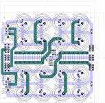
Awful lot of potential current going through those psu board traces.
He, he, hee , I will let you know for sure on this, current is my friend ... 🙂
No one's given the 
I'll send them out as soon as we have a couple people trace them out and make sure that they're A-OK. Takes about 3 weeks for production.
I'll send them out as soon as we have a couple people trace them out and make sure that they're A-OK. Takes about 3 weeks for production.
^^^^ ETA on Boards... ?
Yes, I noticed that. Very well thought out.We don't even have to design bigger output boards. Two output boards will bolt onto each heatsink on our big chassis and you can just daisy chain two boards together on each side to make a monster monoblock.
I also like that you have put N and P channel on separate boards.
It would be nice if you were to also do this for BA2 output. Or you could make these output boards compatible for both F5T and BA2, and just populate the relevant components. It would also reduce manufacturing costs.
Last edited:
Speaker output connection
I don't see where you connect the speaker wire. You supposed to double up the O/P connectors on the input boards?😕
Rush
Ok, I'll post the proposed final designs here because at some point corrections were made. Melon Head, would be very grateful if you'd look them over, then we can send them off to the PCB fab.
I don't see where you connect the speaker wire. You supposed to double up the O/P connectors on the input boards?😕
Rush
I don't see where you connect the speaker wire. You supposed to double up the O/P connectors on the input boards?😕
Rush
It can come out through either TP1 or O/P.
You have O/P at either end of the board for daisy chaining boards, so you always have an unused O/P point
Last edited:
I don't see where you connect the speaker wire. You supposed to double up the O/P connectors on the input boards?😕
Rush
Forget my previous post, while you could do that, I don't think that is ideal.
Probably should have 3 output holes on the front end board:
One for N Channel, One for P Channel, and the 3rd for speaker output.
I really hate to say this, but I don't like the output so close to the input jfets.
This is one thing I remember Nelson saying should be avoided.
I am not sure how close is too close though
A couple of minor suggestions, the output boards, how about moving C1 to the center of the PCB and making as large as possible for maximum decoupling, then beef up the ground track.
A nice touch but probably un-necessary would be if EUVL made some of those natty little heatsinks to thermally couple the JFET's.
A nice touch but probably un-necessary would be if EUVL made some of those natty little heatsinks to thermally couple the JFET's.
this is no problem. it's the same on CViller's boards too.
What is no problem?
The jfets should be moved as close to the front of the board as possible.
I don't like the idea of a small signal travelling to far inside an amp before it is amplified by the first gain stage.
It is worthwhile to perfect this if it is going to be sold at the store.
Hope this is not too much work.
I don't like the idea of a small signal travelling to far inside an amp before it is amplified by the first gain stage.
It is worthwhile to perfect this if it is going to be sold at the store.
Hope this is not too much work.
What is no problem?
output and J-fet distance
but i see it was edited.
I am in the process of building F5 turbo v2. What is the transformer spec I should look for ?
I figured out to be 30VAC -0- -30VAC instead of the 1st version 18V-0-18Vac . I used the calculation from Mr Pass old thread in power supply , which is +/- ( RAIL 8+4 ) /1.4 for rail = + - 32 VDC.
I figured out to be 30VAC -0- -30VAC instead of the 1st version 18V-0-18Vac . I used the calculation from Mr Pass old thread in power supply , which is +/- ( RAIL 8+4 ) /1.4 for rail = + - 32 VDC.
Last edited:
- Status
- Not open for further replies.
- Home
- Amplifiers
- Pass Labs
- F5 Turbo Circuit Boards