Andy,
Can you put me down for 2 Monoblocks, and a couple of extra PSU boards:
4 x V3 output boards
2 x V3 input boards
4 x PSU boards
Thanks
Can you put me down for 2 Monoblocks, and a couple of extra PSU boards:
4 x V3 output boards
2 x V3 input boards
4 x PSU boards
Thanks
only if 1 heatsink is used. most will use 2 heatsinks side by side. then its best as it is.
I am not sure why anyone would prefer to use 2 heatsinks with the V2 combo board. The 50 mm MOSFET spacing is too close. That spacing would be optimal spacing for a heatsink that is 100 mm wide.
Ok guys.
Modified the input board.
There is now a 3 position terminal block.
For Single ended, link the two right hand terminals.
For balanced, farthest right terminal connects to second input board.
Andy
Doesn't anyone want to implement the balanced-X configuration? I am not sure how P3 is incorporated into the balanced-X. Anyone with a suggestion?
Doesn't anyone want to implement the balanced-X configuration? I am not sure how P3 is incorporated into the balanced-X. Anyone with a suggestion?
😀
 😀
😀Hi Andy
Could you change my order to:
1 input board
8 Single output board
and the PSU board
I'm building the V2, I think thats correct. I do like the idea of
"flexibility on heatsink layout"
Thanks
Could you change my order to:
1 input board
8 Single output board
and the PSU board
I'm building the V2, I think thats correct. I do like the idea of
"flexibility on heatsink layout"
Thanks
Hi Andy
Could you change my order to:
1 input board
8 Single output board
and the PSU board
I'm building the V2, I think thats correct. I do like the idea of
"flexibility on heatsink layout"
Thanks
You're just building one mono channel?
You're just building one mono channel?
You'll need two input boards
Is the power supply board complete now? Do all the paths have adequate current handling? The diodes are going to stay on-board etc?
uktoecutter. please change my board order to
4x input boards v3
4x output boards v3
4x psu boards.
thanks
4x input boards v3
4x output boards v3
4x psu boards.
thanks
What you want 2 P3 for, balanced does not need it (I think)
Bksabath
Shows two on Papa's schematic.....
OK
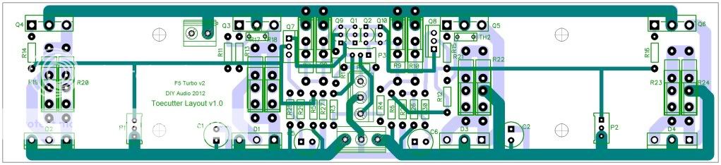
To meet popular demand.
Here's the V2 Combo with mosfets now at 65mm centres and board size reduced to 224mm x 50mm
To meet popular demand.
Here's the V2 Combo with mosfets now at 65mm centres and board size reduced to 224mm x 50mm
OK
To meet popular demand.
Here's the V2 Combo with mosfets now at 65mm centres and board size reduced to 224mm x 50mm
Whoopie!!
UKToecutter:
Your layouts keep getting better. Good work.
My only concern now is the proximity of the JFETs to the output signal and to the feedback resistors R7-R10. My concern feedback resistors is that their temperature changes dramatically with the output level, and there is likely to be significant thermal coupling to the JFETS. Of course, there is a significant time lag in this coupling, but it could cause some problems for bias balance.
The center of the board could be de-cluttered by moving the cascode circuit to the empty areas away from the center, allowing the JFETs to move to near the power connector.
Another possibility is to move the feedback
- Status
- Not open for further replies.
- Home
- Amplifiers
- Pass Labs
- F5 Turbo Circuit Boards