It's probably better to arrange as CRCC, to keep losses to a minimum. This is a power amp after all...
(6) 0.47 3W resistors in parallel (as in the original PSU) is roughly an 18W 0.1ohm resistor.
You could search for something like that, or just parallel a bunch of the 3W resistors, which is a lot easier.
Many thanks Gents
I now believe I have a way forward. (CRCC).
As I have some Dale .47ohm 1%, I will be using these. (would that be six or seven).
One further question ;I have some BYW 99W 200 for the rectifiers, or is it worth going the extra mile and purchase some MUR 3020WT.
The BYW will be very good for the PSU. Use them. 🙂
The MUR are needed for the 'turbo' diodes in the amp circuit, their specific R vs I is used in the amp to get the turbo effect. (See original article for more info)
The MUR are needed for the 'turbo' diodes in the amp circuit, their specific R vs I is used in the amp to get the turbo effect. (See original article for more info)
I suppose I should have asked this before ordering, but what about ETU3006 rectifiers? (For both an F5 and an F3.)
http://www.mouser.com/ds/2/427/vs-etu3006m3-250141.pdf
The Vf is a bit high (1.4V), but that won't sink me, will it?
http://www.mouser.com/ds/2/427/vs-etu3006m3-250141.pdf
The Vf is a bit high (1.4V), but that won't sink me, will it?
look at the datasheet again.I suppose I should have asked this before ordering, but what about ETU3006 rectifiers? (For both an F5 and an F3.)
http://www.mouser.com/ds/2/427/vs-etu3006m3-250141.pdf
The Vf is a bit high (1.4V), but that won't sink me, will it?
Fig 1 shows the typical Vf vs Ia for three temperatures.
@1.4Vf the diode is passing between 30A and 60A
@0.7Vf the diode is passing <5A
It is little different to many other Power Diodes.
Thanks for that, Andrew. I had seen that, but incorrectly assumed that other rectifiers would have similar curves. In fact, aside from having a broadly positive slope, they seem to be all over the map.
sorry, maybe and already been told here but, x F5 tube v2 that transformer I have to use; 600 w / 800w, 2x18 or 2x24 ??? thank you
F6 Turbo v2 newbie question
The FQA output FETs have quite a difference in Rds(on) or/and Gfs. If I want to find a suitable alternative to the FQAs in the original schematic, which of the two are most important to match?
Thx for any answer!
🙂 morten
The FQA output FETs have quite a difference in Rds(on) or/and Gfs. If I want to find a suitable alternative to the FQAs in the original schematic, which of the two are most important to match?
Thx for any answer!
🙂 morten
I'm planning to try some different settings for P3 but don't have access to a distorsion analyser.
Which way should i turn P3 to increase 2nd harmonics vs not?
Would i be able to see the difference in a simple oscilloscope or is the distorsion to low even in the extremes of the potentiometer?
Which way should i turn P3 to increase 2nd harmonics vs not?
Would i be able to see the difference in a simple oscilloscope or is the distorsion to low even in the extremes of the potentiometer?
sorry, maybe and already been told here but, x F5 tube v2 that transformer I have to use; 600 w / 800w, 2x18 or 2x24 ??? thank you
everything is in article .... all you need is to read it 100 times and use some brain and one calculator
so , F5T V2 , xformer needs to be 2x24Vac (or written differently - 48VCT (48Volts with center tap))
dissipation is in range of 100W per channel , so use no less than 300VA xformer per channel ....... or 600VA if transformer is common for both channels
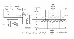
decent PSU is shown on page 11 in article
I'm planning to try some different settings for P3 but don't have access to a distorsion analyser.
Which way should i turn P3 to increase 2nd harmonics vs not?
Would i be able to see the difference in a simple oscilloscope or is the distorsion to low even in the extremes of the potentiometer?
nope , just leave it in mid position
confirm that with ohmmeter prior to soldering it on pcb
well , both are important
anyway , all adequate parts are in +/-15% bracket for both characteristics , comparing to parts Papa originally used
however , remember what Pa wrote, these words are your guide in general :
anyway , all adequate parts are in +/-15% bracket for both characteristics , comparing to parts Papa originally used
however , remember what Pa wrote, these words are your guide in general :
A number of DIYers have speculated on or even tried the Toshiba 2SK1530
and 2SJ201 Mosfets. These are really nice (discontinued) audio transistors
and are very fine for F5's, but keep in mind that with a 12 amp rating they
have a smaller maximum current than the Fairchild parts. This will not
prevent them from sounding very good, however, and I do recommend them
in general
well , both are important
anyway , all adequate parts are in +/-15% bracket for both characteristics , comparing to parts Papa originally used
however , remember what Pa wrote, these words are your guide in general :
I still don't get it. The datasheets show this:
FQA12P20: Rds = 0.35 - Gfs = 6,6
FQA19N20: Rds = 0,12 - Gfs = 16
Is the amplifier designed with these differences in mind or is closer matched FETs better?
thank youeverything is in article .... all you need is to read it 100 times and use some brain and one calculator
so , F5T V2 , xformer needs to be 2x24Vac (or written differently - 48VCT (48Volts with center tap))
dissipation is in range of 100W per channel , so use no less than 300VA xformer per channel ....... or 600VA if transformer is common for both channels
decent PSU is shown on page 11 in article
I still don't get it. The datasheets show this:
FQA12P20: Rds = 0.35 - Gfs = 6,6
FQA19N20: Rds = 0,12 - Gfs = 16
Is the amplifier designed with these differences in mind or is closer matched FETs better?
they certainly weren't random chosen
so , as you can see , you can use pretty broad range of parts ...... in any case, do not go much higher than 0R35 for Rds and not much lower than 6.6 for Gfs
they certainly weren't random chosen
so , as you can see , you can use pretty broad range of parts ...... in any case, do not go much higher than 0R35 for Rds and not much lower than 6.6 for Gfs
Thx, it makes sense keeping the values within this range! 🙂
- Home
- Amplifiers
- Pass Labs
- F5 Turbo Builders Thread