F5t Mono's build
ongoing works...
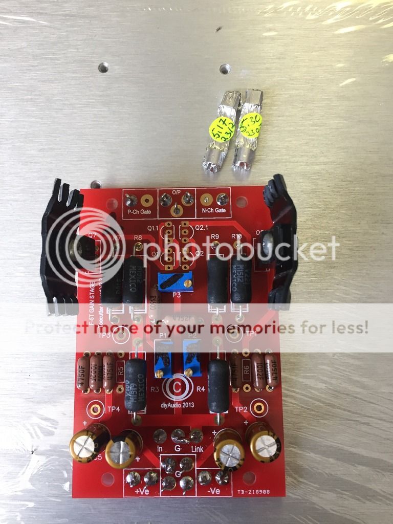
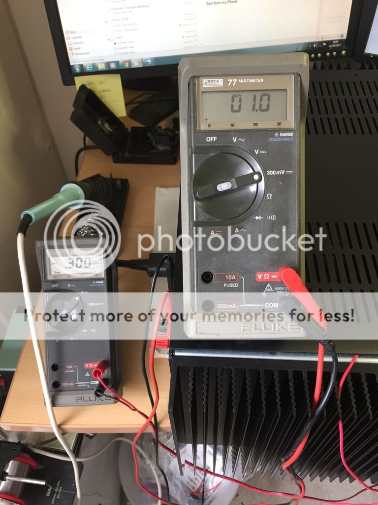
48v rails running 300mv of bias, warm, = just right.
ongoing works...


48v rails running 300mv of bias, warm, = just right.
Last edited:
I was going to explain away each photo but I ran out of time uploading them. (30 mins edit time seems stingy) I use photobucket which is a pain to use of late.
Attach your pics.
Since the first post is editable for ever by the originator, you can add script at the time of posting or later.
You can add further script some days/weeks/months down the road. You can remove errors if any come to light.
Just attach your pics, to your new Thread where you can give as many details as you want.
ongoing works...
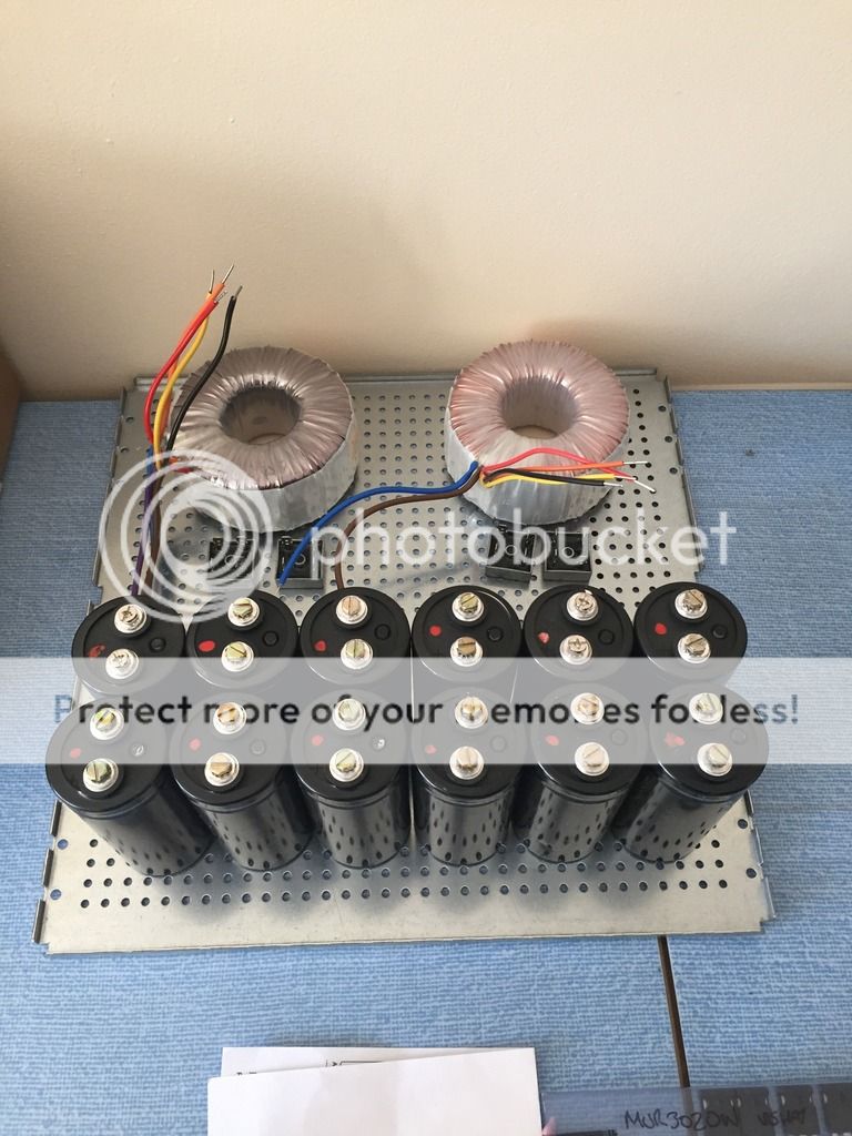
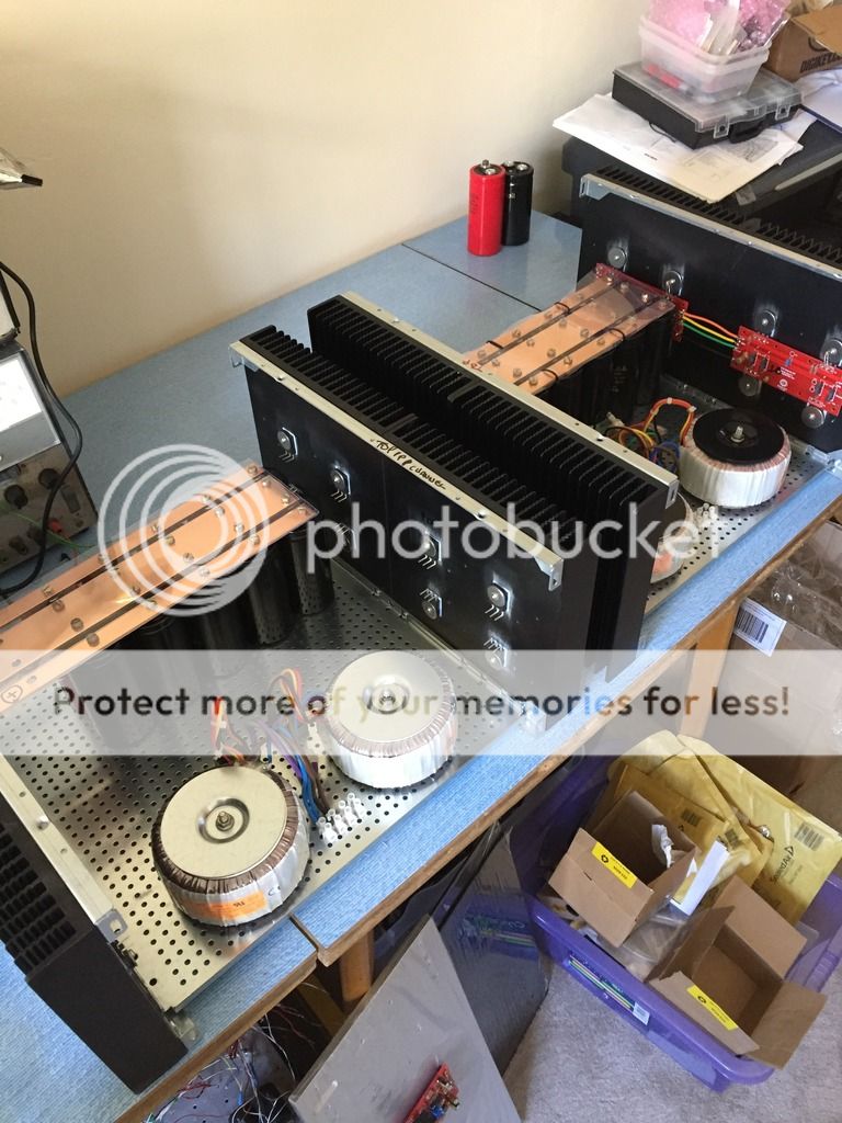
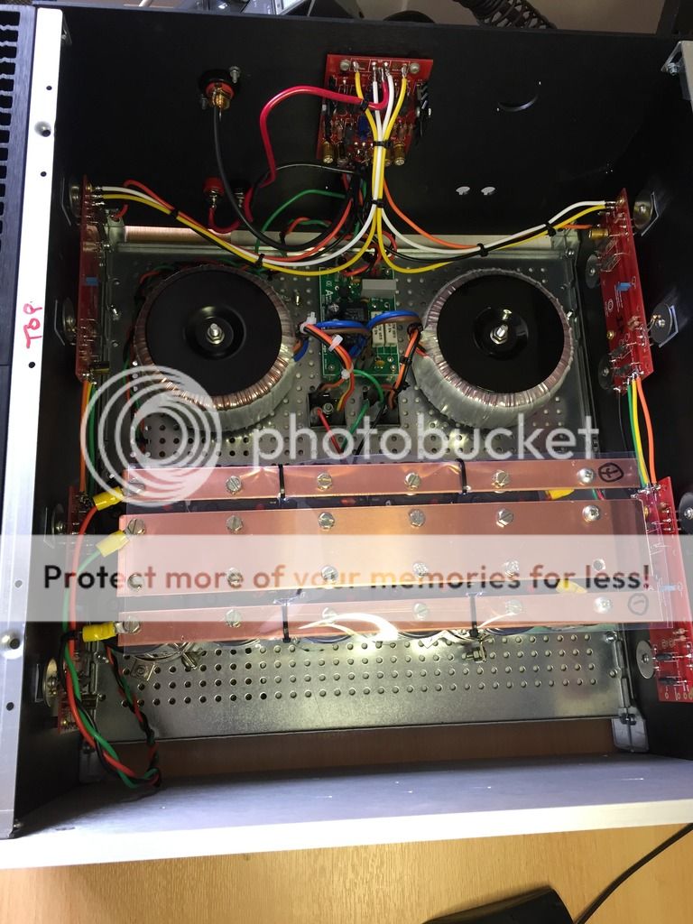
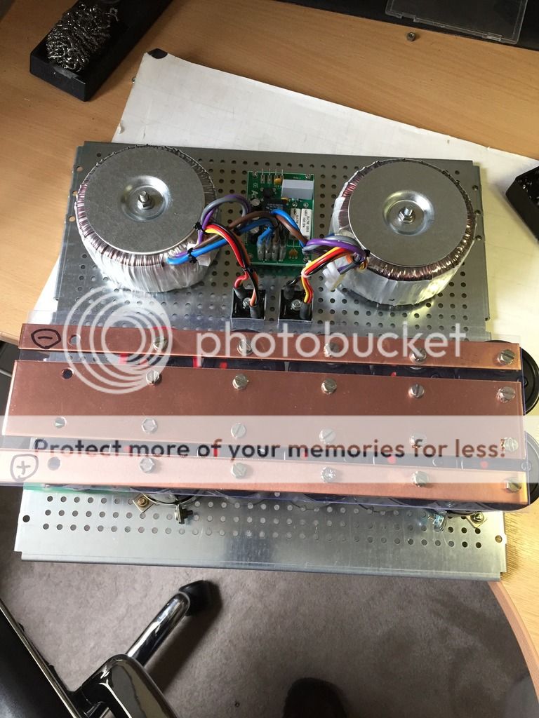
Looking very nice! Why do you have four transformers? One for POS rail, one for NEG, and then the same again in the other monoblock?
Also, what inrush limiter / turn-on delay boards are these?
Looking very nice! Why do you have four transformers? One for POS rail, one for NEG, and then the same again in the other monoblock?
Also, what inrush limiter / turn-on delay boards are these?
Yes, one transformer per rail. (two in each mono) I already had one pair of transformers 300va 0-35 0-35. So only had to buy two more. Giving 600va per monoblock.
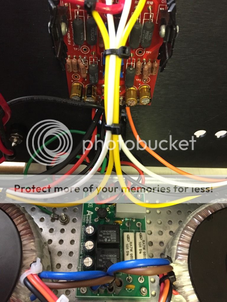
The 'soft starts' are from a company called Avondale Audio here in the UK the product is SSM2.
Thanks for the info AndrewT
I do have a F5V3 turbo for repair. I have no schema.Does anyone knows if this is a cascode F5, so that a higher power than the +/- 32 V printet on the PCB can be used?
Eivind S
Eivind S
Pictures of JIM Audios F5V3 Turbo PCB :
Mosfet high power 100W pure class A amplifier thick PCB turbo V3 stereo !! | eBay
Eivind S
Mosfet high power 100W pure class A amplifier thick PCB turbo V3 stereo !! | eBay
Eivind S
Pictures of JIM Audios F5V3 Turbo PCB :
Mosfet high power 100W pure class A amplifier thick PCB turbo V3 stereo !! | eBay
Eivind S
This board is showing only one pair of jfets, it could be used at 48v but you would need to piggy back another pair of jfets (Cascode)
So +/- 42V DC with one pair of jfets will be "safe"?
Two pairs of jfets, are the mounted in parallell with the one pair on the PCB?
Eivind S
Two pairs of jfets, are the mounted in parallell with the one pair on the PCB?
Eivind S
Talking about V2 or V3 with diodes, is there any smart a..s (only in a good sense 🙂 - I mean, who knows what he does) who had tried to attach thermoswitch to each output device to prevent that thermal runaway consequences? Or who could explain if/why it would not work.
Did. Works fine.
Do need to watch total drain resistance on the jfets though, it needs to be close to the original figure else the OLG drops a bit.
Do need to watch total drain resistance on the jfets though, it needs to be close to the original figure else the OLG drops a bit.
My F5 is now finished, but I have a little problem now, when the power is on there is a silent hum sound on my right channel. If I connect only the left side of my F5 there is no hum sound at all. When I connect both of them and I touch my Case of the Amp the hum sound is also gone. Whats the meaning of this ?
I solved the problem by myself, but I have a little problem left. If I switch the amp on, it hums a little and if I knock with my finger on the front casing the hum sound is completely gone. If I switch it off and on again it's there again... Is my Volume Potentiometer faulty ? (It's an old Alps 100K). Or do I still have problems with the earthing ?
regards
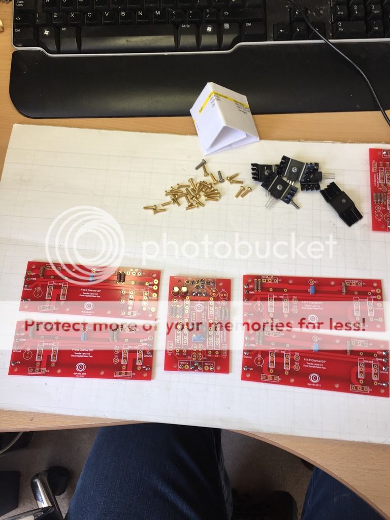
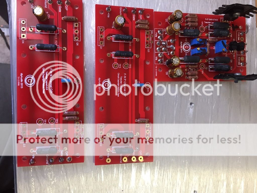
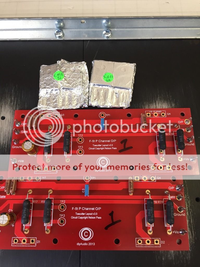
So, moving on with my mono build project and the second mono coming together..
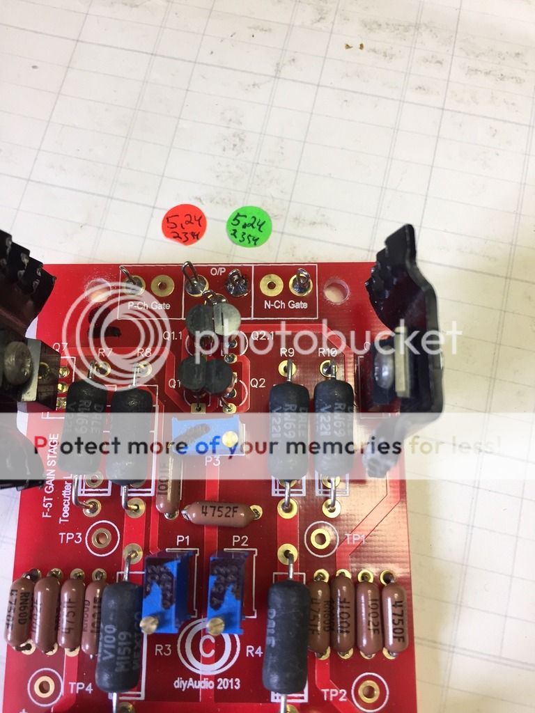
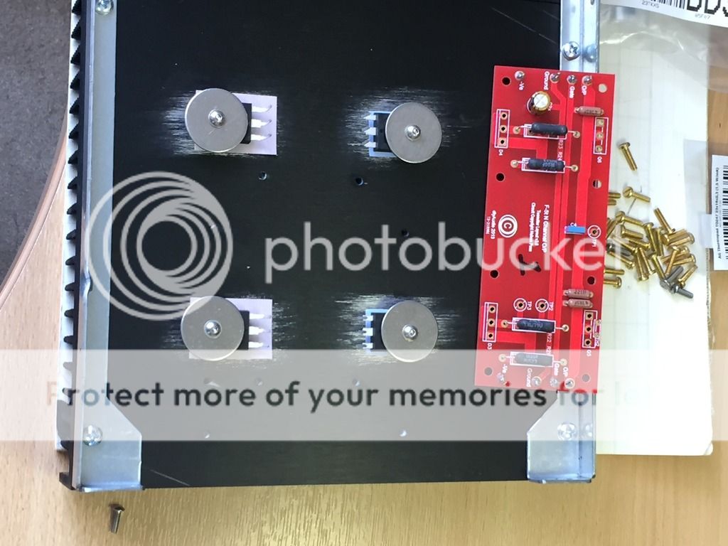
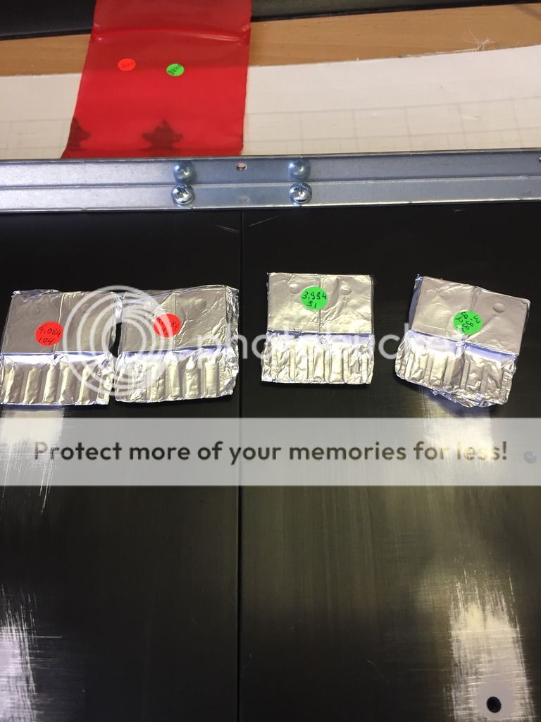
Quad jfets arrived...and installed. These were the last bits Ive been waiting for...
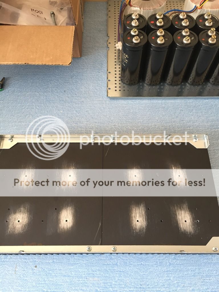
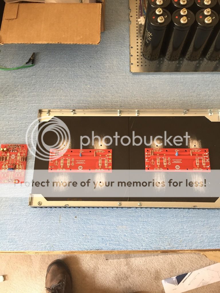
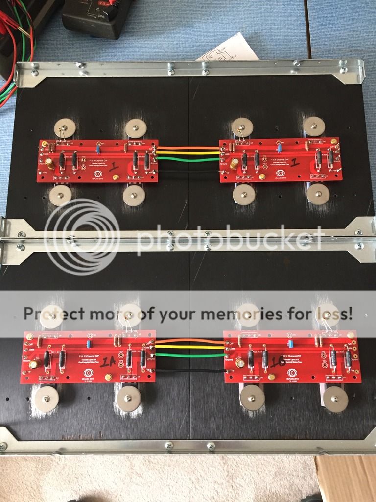
Building up....putting the jigsaw together..just some wiring to be done and the initial bench PSU power up.
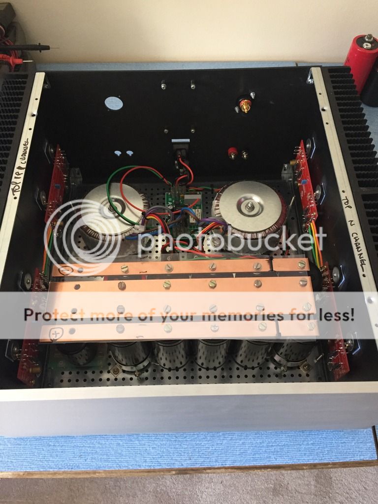
nearly done....
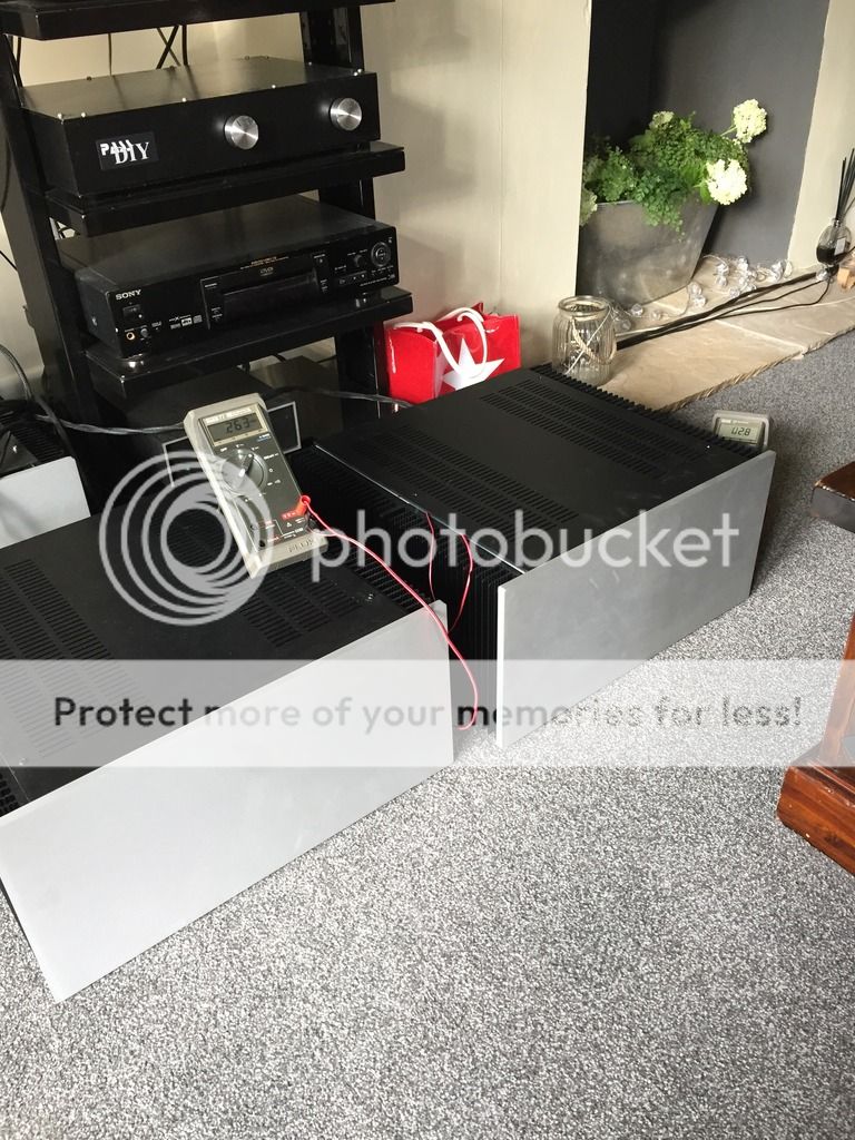
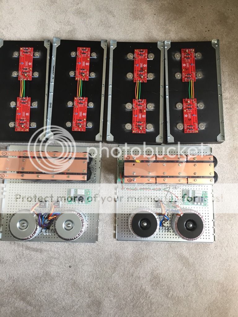
A three hour soak at .3v bias and less than 5mv . All good.
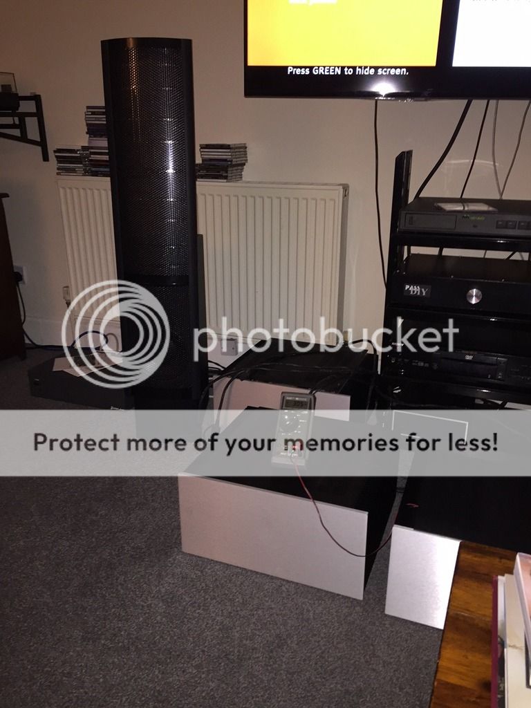
And the all important listening test......what can I say...WOW...The stereo F5t amp consigned to the lower ranks at the rear.

Quad jfets arrived...and installed. These were the last bits Ive been waiting for...

Building up....putting the jigsaw together..just some wiring to be done and the initial bench PSU power up.

nearly done....

A three hour soak at .3v bias and less than 5mv . All good.

And the all important listening test......what can I say...WOW...The stereo F5t amp consigned to the lower ranks at the rear.
Last edited:
That intermittant hum could be a stray wire touching the chassis and creating a loop.I solved the problem by myself, but I have a little problem left. If I switch the amp on, it hums a little and if I knock with my finger on the front casing the hum sound is completely gone. If I switch it off and on again it's there again... Is my Volume Potentiometer faulty ? (It's an old Alps 100K). Or do I still have problems with the earthing ?
regards
Did. Works fine.
Do need to watch total drain resistance on the jfets though, it needs to be close to the original figure else the OLG drops a bit.
Thanks for reply Sangram, but I did not understand - re total drain resistance- why would it change? I haven't assumed any mods in the original schematics, only extra thermoswitches, triggering, say, at 70-75 Celsius degrees and disconnecting from mains.
Thanks for reply Sangram, but I did not understand - re total drain resistance- why would it change? I haven't assumed any mods in the original schematics, only extra thermoswitches, triggering, say, at 70-75 Celsius degrees and disconnecting from mains.
Sorry, thought you were referring to thermistors.

- Home
- Amplifiers
- Pass Labs
- F5 Turbo Builders Thread