So which boards to use
Whichever pleases you ?

Cascode devices can be bypassed with a wire link, common cathode diodes can be parallel connected to source resistors with wires.
Ahhh, not the PS275, but the PS257. Why didn't you say so.
The thermal resistance number for fan blown mentioned there is at 5m/s air velocity, don't think you'd want that.
That heatsink model in 150mm height does about 0.25 C/W, say 0.35 C/W derated for 50C operating temperature.
With a fan blowing at 2m/s, one heatsink would do half that number, ~0.175C/W.
Two of the fan/heatsink setups would handle the 260W dissipation, at under 25C above ambient.
(quicky wet finger estimate)
Means 4 heatsinks and 4 fans for stereo.
Scary, no ?
Addendum : Option would be to mount two heatsinks facing eachother, forming a duct, with one 120mm fan mounted on them. Would require a DIY plenum between fan and heatsinks to make the crossover from 120mm to 178mm.
Balanced/bridged with 25V (to 35V) rails is the most sensible choice for an F5T build, btw (imo)
Last edited:
> Ahhh, not the PS275, but the PS257.

That's the one. The table gives this as 300mm long, which will be halved and put back to back and made into a tunnel with a fan at one end. (Comme ihquam)
> Cascode devices can be bypassed with a wire link, common cathode diodes can be parallel connected to source resistors with wires.
Yes Yoecutter's balanced input boards with individual boards for each output device is favourite.
Last edited:
Think output level of 35V in 2 ohm, with 75V rails.
40V drop between drain and source, 17.5A current going through the mosfets : 700W dissipation.
Worst load for an output stage occurs when the product of output current times voltage drop is highest.
A sine curve shows that this happens below 50 percent of max output.
Pushing out full power is relatively harmless for an output stage : high output current, but low Vds.
OK ... get yah ....!!!!
Just one thing that may be worth a mention
Your CL60 or CL 30
Bigh Traffos with Loads of C and loads of current at Idle
The Surge supressors are going to work overtime and going to get hot
You lot beter start to think about By passing them with a relay maybe😀
Your CL60 or CL 30
Bigh Traffos with Loads of C and loads of current at Idle
The Surge supressors are going to work overtime and going to get hot
You lot beter start to think about By passing them with a relay maybe😀
2 ohm, with 75V rails.
Jacco, just for curiosity's sake, how many input pairs would I need for 8 output pairs, 75V rails and 2 ohm load?
Many thanks
For a MHz, i'd think 28 pairs.
It's a shame you don't like sharing your knowledge.
Ask the right question.
State the bias current and the operating Tc for your proposed output stage and just maybe someone could help.
But since it's
State the bias current and the operating Tc for your proposed output stage and just maybe someone could help.
But since it's
why should any Member waste their time?just for curiosity's sake
Ask the right question.
State the bias current and the operating Tc for your proposed output stage and just maybe someone could help.
But since it's why should any Member waste their time?
Don't know why you wasted yours with me then. And sorry if I'm a beginner and don't know exactly what I should state to have my question answered. Stupid me that thought everyone would be welcome here.
8 times as many output devices.
70V out instead of 20V, 3.5 times the voltage stretch.
8 times 3.5 is 28 JFET pairs per channel.
Use 1 pair of JFETs, 8 MOSFETs in parallel, 75V rails : ~35KHz (1 MHz divided by 28) ~57Khz with the revised feedback.
Nice subwoofer amp
Maybe 12 pairs if you take the 32V of the V2 as a reference.
Mr Popa managed to parallel as many as 4.
Easier to make a small high quality power amp than a biggy. (the prime reason for FW's existence)
Maybe you should read the F5T article thoroughly.
Last edited:
Yep, with more gain.
800 with 2 pair, so ~200 with 8 pair.
From 28V peak to 70Vpeak, 200 divided by 2.5, makes 80KHz bandwidth.
To get back to 800, minimum would be 10 JFET pairs.
(28 for the original F5)
10, 12, or 28.
6 of one or half a dozen of the other, all the same.
800 with 2 pair, so ~200 with 8 pair.
From 28V peak to 70Vpeak, 200 divided by 2.5, makes 80KHz bandwidth.
To get back to 800, minimum would be 10 JFET pairs.
(28 for the original F5)
10, 12, or 28.
6 of one or half a dozen of the other, all the same.

Hehe......
little known fact about the R5 turbo - the turbo charger was rated at 50 'in stage' Minutes !!!!!
An F5 Turbo might run as hot as one of these hyper active shopping trollies. I'm lucky enough to know some one who owns one AND I've had a few rides in it, it makes some of the most amazing whooshes, bangs, burps and pinging noises I've ever heard......no room for ICE - not that you'd be able to hear it.
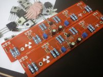
Start building a V1 without P3, hope everything going smooth 😀
PS, life without a decent camera is a crime 🙁
PS, life without a decent camera is a crime 🙁
Attachments
Last edited:
F 5
Hi chchyong89,I would have that board.Where you got from.Can you give me a detail please.Start building a V1 without P3, hope everything going smooth 😀
PS, life without a decent camera is a crime 🙁
Hi chchyong89,I would have that board.Where you got from.Can you give me a detail please.
😕
I sent my layout for fabrication. Try paying attention this thread, maybe someone will run a group buy😱
...looks like this. Oops, that's a R5 Turbo.
What's a F5 Turbo?
Hehe......
little known fact about the R5 turbo - the turbo charger was rated at 50 'in stage' Minutes !!!!!
An F5 Turbo might run as hot as one of these hyper active shopping trollies. I'm lucky enough to know some one who owns one AND I've had a few rides in it, it makes some of the most amazing whooshes, bangs, burps and pinging noises I've ever heard......no room for ICE - not that you'd be able to hear it.
OT...🙂 I have an 300 bhp one here , great little car no brakes .... 😱
bandwidth?
I'm a beginner. I understand basic concepts. What does 'bandwidth' mean for an amplifier? I don't quite understand what 800Khz bandwidth means and how it is better or worse than 80Khz. Maybe someone could expand on this?
800 with 2 pair, so ~200 with 8 pair.
From 28V peak to 70Vpeak, 200 divided by 2.5, makes 80KHz bandwidth.
To get back to 800, minimum would be 10 JFET pairs.
I'm a beginner. I understand basic concepts. What does 'bandwidth' mean for an amplifier? I don't quite understand what 800Khz bandwidth means and how it is better or worse than 80Khz. Maybe someone could expand on this?
- Home
- Amplifiers
- Pass Labs
- F5 Turbo Builders Thread