The resistance parallel to the source resistance makes vitually no contribution to the noise performance of the amplifier.
You could use 10M instead of 100k and you will not be able to hear any extra noise.
The Source impedance dominates the noise performance.
You could use 10M instead of 100k and you will not be able to hear any extra noise.
The Source impedance dominates the noise performance.
Hello everyone. I am finally populating the boards.
but I only sourced 10k thermistors instead of 4k7.
Can I install them or should I omit them all together?
Thanks
but I only sourced 10k thermistors instead of 4k7.
Can I install them or should I omit them all together?
Thanks
The correction range of a 10k unit will be much worse. Also the resistance ramp is going to be different, you will need lower Idss FETs and higher drain resistors. You could add a 4k7 resistor in parallel to the thermistor but even that is a bit unpredictable.
Help placing transistors.
Hello all 🙂
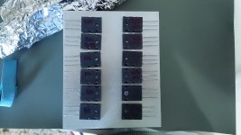
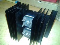
I decided to build my F5 aircooled. So I ordered 2x Conrad Heatsinks MF18-151.5. They measure 12.5x15.2 cm, and I'm going to use them back-to-back, to build an air tunnel. I would like to discuss the best spacing for the transistors, before I tap the holes. I'm going to use one heatsink per channel, each channel with 6 Nmos and 6 Pmos, each group in a row.
Thank you very much
Daniel
Hello all 🙂
I decided to build my F5 aircooled. So I ordered 2x Conrad Heatsinks MF18-151.5. They measure 12.5x15.2 cm, and I'm going to use them back-to-back, to build an air tunnel. I would like to discuss the best spacing for the transistors, before I tap the holes. I'm going to use one heatsink per channel, each channel with 6 Nmos and 6 Pmos, each group in a row.
Thank you very much
Daniel
Attachments
Hello all 🙂
I decided to build my F5 aircooled. So I ordered 2x Conrad Heatsinks MF18-151.5. They measure 12.5x15.2 cm, and I'm going to use them back-to-back, to build an air tunnel. I would like to discuss the best spacing for the transistors, before I tap the holes. I'm going to use one heatsink per channel, each channel with 6 Nmos and 6 Pmos, each group in a row.
Thank you very much
Daniel
I wouldn't recommend doing this unless you use a fan.
I wouldn't recommend doing this unless you use a fan.
Of course I'll do. I'm using a 120mm Noctua fan based on lhquam experience. Do you have any suggestions on the transistors placement?
Thanks
As long as there is plenty of space underneath and above you'll probably get a bit better cooling than standard configuration. But, compare the radiating surface of your sinks with the 4U case in the store that many people use for an F5 - you have less total than a single side of the 4U case. Class A amps are heavy metal projects. A single mosfet on each sink about 1/3 of the way up and you have enough sink for one channel without a fan. Make another tunnel for the other channel.
But, with all those mosfets lined up, it looks like you're thinking F5 turbo. You really need a fan (probably running fast) to dump the 150+ W per channel with sinks that size. I'd get four more of those profiles and use 3 per channel if you are looking at a 3-4 pair F5T. If you are thinking 6 pairs per channel, then you'll need even more heat sink. Take a look at the store's 5U case - that's enough for a 4 pair monoblock.
EDIT: Just saw that you posted while I was typing. Just space them evenly, roughly as you have them laid out in your picture. Trying to optimize the temperature drop gains very little when fan cooled.
Last edited:
Of course I'll do. I'm using a 120mm Noctua fan based on lhquam experience. Do you have any suggestions on the transistors placement?
Thanks
This is a subtle issue. Heat sinks are only rated for UNIFORM heat flow through the entire surface, not at discrete spots.
The rear exposed metal tab area of each (not the mounting screw) could be centered between the two sides, although they also could be staggered a little, and use more of the fins more effectively.
The other question is how to space them vertically. Most would divide the vertical length into equal parts and center the devices in each part.
I suggest that the insulator choice will be as important as placement on the sink, mica is good. Also, you could consider clamping them to the sink, rather than screwing them down with their mounting holes. If you do screw them down, use the proper torque as rated. Otherwise will affect the heat transfer. The fins ideally should be vertical, with air blowing upward, fan on the intake (bottom) so it won't get too hot.
Amps Up and Running
Hi All,
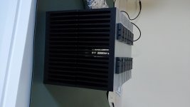
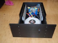
I finally had time to finish the chassis I have modified to fit a big toriod, 2.4kva, and eventually the 8 71k uf of cap when they finally get here (12 weeks lead time). The parts were black andonized and look nice and throw off the 500w of standing idle bias. Tweaked the bias so the heat sink is around 50C when stabile. From the pictures you can see the air holes in the bottom plate and top that I drilled. This is my SA/1 copies. Now that I can build the chassis from scratch AND look good I will make another single chassis for the F5 turbo.
Have a good one,
John
Hi All,
I finally had time to finish the chassis I have modified to fit a big toriod, 2.4kva, and eventually the 8 71k uf of cap when they finally get here (12 weeks lead time). The parts were black andonized and look nice and throw off the 500w of standing idle bias. Tweaked the bias so the heat sink is around 50C when stabile. From the pictures you can see the air holes in the bottom plate and top that I drilled. This is my SA/1 copies. Now that I can build the chassis from scratch AND look good I will make another single chassis for the F5 turbo.
Have a good one,
John
Attachments
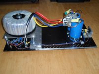
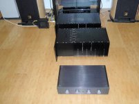
Excellent job, one recommendation though, move the rectifiers to the chassis base to keep the heat away from the capacitors, it will also help to remove some of the heat from the rectifiers.
Excellent job, one recommendation though, move the rectifiers to the chassis base to keep the heat away from the capacitors, it will also help to remove some of the heat from the rectifiers.
Yes, right now it appears that the capacitor terminals, and therefore the capacitor internals, are being heated up by the rectifier bridges.
Rectifiers to chassis
When I upgrade the caps from 2 to 8, with a 3 mh choke in the middle of the bank, then I will move the rectifiers. Interestingly though the heavy aluminum angle bracket I used to bridge the caps for a common and mount the bridges doesn't even get warm.
Have a good one,
John
When I upgrade the caps from 2 to 8, with a 3 mh choke in the middle of the bank, then I will move the rectifiers. Interestingly though the heavy aluminum angle bracket I used to bridge the caps for a common and mount the bridges doesn't even get warm.
Have a good one,
John
ClassAB amplifiers use quite low currents most of the time.
The rectifiers run cold, except when you have a drunken party.
ClassA amplifiers consume lots of current all the time.
The rectifiers usually need heatsinks to prevent them getting excessively hot.
Even with heatsinks they run warmer than a naked ClassAB rectifier.
Protect your capacitors AND fit a heatsink.
- Home
- Amplifiers
- Pass Labs
- F5 Turbo Builders Thread