it is
don't forget insulators , though
Having forgot them on my first F-5, which is documented here somewhere or the other had to undo 16 of them and put sil pads underneath. Never forgot that lesson. Plus, and this really hurts, I put "grease" between the backs of the diodes and the case floor...... had to clean all that up to. Hard lesson to learn, but that one stuck with me!
Russellc
Here's what Papa said about th e JFETS now in the store:
"The B through D and most of the A would not be a problem
for the ACA, and a slight adjustment would allow down to the
2.5 mA figure without problems.
Most of my projects would want a B or C grade as most desirable,
but it’s not a big deal."
"The B through D and most of the A would not be a problem
for the ACA, and a slight adjustment would allow down to the
2.5 mA figure without problems.
Most of my projects would want a B or C grade as most desirable,
but it’s not a big deal."
BOM (Thanks UKToecutter!!)
F5Tv2 -
http://www.diyaudio.com/forums/attachment.php?attachmentid=374043&stc=1&d=1380542501
F5Tv3 -
http://www.diyaudio.com/forums/attachment.php?attachmentid=374044&stc=1&d=1380542501
Please look these over and see if there are any omissions or needed corrections. 🙂
F5Tv2 -
http://www.diyaudio.com/forums/attachment.php?attachmentid=374043&stc=1&d=1380542501
F5Tv3 -
http://www.diyaudio.com/forums/attachment.php?attachmentid=374044&stc=1&d=1380542501
Please look these over and see if there are any omissions or needed corrections. 🙂
Attachments
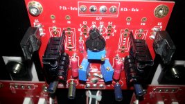
Hi 6L6,
I suggest to revise the P1 and P2 with the 3296X that have the lateral regulation that is more easy to turn during the bias.
I see that also the new PCBs in the Store now have the serigraph with the lateral.
In the photo you can see what I mean. Now I can bias the ampli easier with the enclosure closed.
Regards,
Enrico
Attachments
emyeuoi,
"I see that also the new PCBs in the Store now have the serigraph with the lateral"
What does this mean?
"I see that also the new PCBs in the Store now have the serigraph with the lateral"
What does this mean?
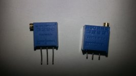
sorry for my bad english... I mean that in the store you can found the photo of the PCBs of the F5T. There you can see that the serigraphy has been modified and now the screw for regulate the trimmer is in the "lateral" side and not in the "top".
I attach a photo to show you what I mean... the 2 trimmers with the "lateral" regolation and the "top" regolation.
I attach a photo to show you what I mean... the 2 trimmers with the "lateral" regolation and the "top" regolation.
Attachments
Ah, I see.
In actual fact the silkscreen (serigraph) is agnostic of which 3296 variation you choose as the screw is not shown.
It is then left for the individual to choose.
The BOM is only a guideline
In actual fact the silkscreen (serigraph) is agnostic of which 3296 variation you choose as the screw is not shown.
It is then left for the individual to choose.
The BOM is only a guideline
Offcourse... was just a suggestion because I realize only at the end that is very difficult to bias the ampli with the encloser close and the screw on top and I loose a lot of time to found the ones lateral. I have also to desolder the old one etc.
Maybe is good for everybody to know about.
Regards,
Enrico
Maybe is good for everybody to know about.
Regards,
Enrico
AudioSan
Well spotted.
At least the part number is correct.
I think my brain must have farted as I was typing it out!!!
Well spotted.
At least the part number is correct.
I think my brain must have farted as I was typing it out!!!
Attachments
actualy no. R11/R12 should only be used on one P-ch board and one N-ch board.
also R26 is missing. R25,26,27 and 28 may differ in value. depending on your rail voltage and the wanted cascoded voltage.
also R26 is missing. R25,26,27 and 28 may differ in value. depending on your rail voltage and the wanted cascoded voltage.
Last edited:
- Home
- Amplifiers
- Pass Labs
- F5 Turbo Builders Thread