Lovely Both sound very good, this gives me a reason to relax and wait a bit and get on with other things! I love how messy my bedroom has become in this build process 😀
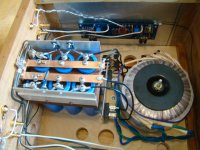
here is a picture of my f5 power supply...couldn't get much simpler. I have done the same type with proto board and snap in caps.
Thats pretty good, maybee I should do that! I also have 2x Rectifiers laying around like them. The diodes im using at the moment are getting a bit hot, can't actually remember now the difference between the normal rectifiers and the MUR ? diodes.
Whats between your caps ?
Hmm u got me thinking now.
Last edited:
.1r caddock mp930 resistors. could be others, but these were convenient.
copper bar could be on hand copper wire.
copper bar could be on hand copper wire.
Where buy these brackets?
Congratulation for your nice work!
If it is posible i want to know where buy theese brackets
best regards.
thimios.
Hi dear .Finished wiring up a V2 monoblock last night. I am in the process of powering up the first time right now. I'm kinda guessing that P3 gets set near the middle of its range.
Anyhow, here are some photos. New UKToecutter boards, diyA chassis.
The plan is to get it up and running (biased) by tonight.
I'll post more details a bit later when I've got a spare moment and the amp's done.
-Nelson
Congratulation for your nice work!
If it is posible i want to know where buy theese brackets
best regards.
thimios.
Attachments

Those brackets come with the chassis' available from diyAudio Store.
We're getting in another batch of chassis in a month. ( i know, some may be skeptical) I believe that chassis is the 4U model. The brackets aren't available in the store but HiFi 2000 in Italy might sell them separately
We're getting in another batch of chassis in a month. ( i know, some may be skeptical) I believe that chassis is the 4U model. The brackets aren't available in the store but HiFi 2000 in Italy might sell them separately
Hi dear .
Congratulation for your nice work!
If it is posible i want to know where buy theese brackets
best regards.
thimios.
Can I use 2 rectifiers to get my +/- for the F5t but using a centre tapped transformer ? all the diagrams for PSU I see the transformer has 4 secondary wires, mine only has 3.
Nice schematic . Papa ans zen mod have suggest this earlier in the pass threads.this looks the business.
Power Supply for Power Amplifiers
Just found out this is no good unless i want 44 volts DC on my F5t lol
My transformer is 2x24 so got to find another solution.
My transformer is 2x24 so got to find another solution.
Is modifing this to work with centre tapped going to just go up in smoke ?
attaching the middle AC1 and 2 together as the centre-tap, im just focusing on the bridges, ignore the rest.
attaching the middle AC1 and 2 together as the centre-tap, im just focusing on the bridges, ignore the rest.
An externally hosted image should be here but it was not working when we last tested it.
Last edited:
it's better this way
connect +PGND and -PGND , and you have pretty clean gnd point
though - if you want it your way - connect lower AC1 with upper AC2 , then use single Graetz
connect +PGND and -PGND , and you have pretty clean gnd point
though - if you want it your way - connect lower AC1 with upper AC2 , then use single Graetz
Thanks, sorry If I sound a bit impatient at times im just eager, do appreciate the help! 🙂
yes if i connected +PGND and -PGND it would be good however what I find hard to get my head round is that my transformer only has 3 wires on secondary so i presume i cannot actually make that previous circuit and will have to use Single Graetz as only option
or
this circuit which with 2x24v would be too high voltage anyway, this is preferred to me by far but a shame as the output voltage would be too high 🙁
An externally hosted image should be here but it was not working when we last tested it.
Last edited:
Actualy maybe this last schematic wouldn't be too high voltage! forgive my insanity, about to try it.
- Home
- Amplifiers
- Pass Labs
- F5 Turbo Builders Thread